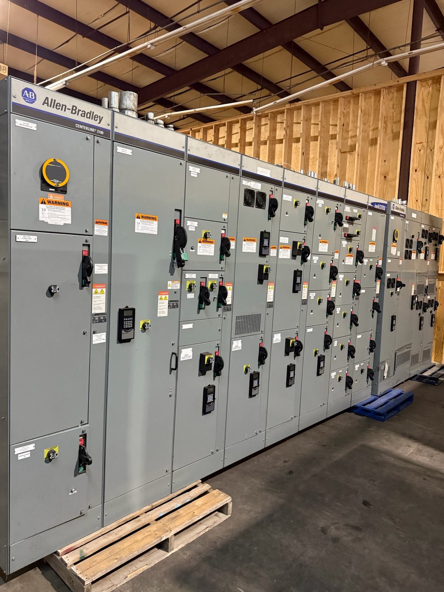
Choose a switch-and-fuse or breaker arrangement
Start by defining what each compartment must do: incoming isolation, feeder protection, transformer protection, bus sectionalizing or another function. A load-interrupting switch paired with fuses and a circuit breaker are not interchangeable choices. The appropriate arrangement depends on the system design, load characteristics, protection coordination and operating sequence. Share a one-line diagram and identify the equipment served so the proposed configuration can be evaluated against the actual application.
For a switch-and-fuse lineup, specify the intended fuse type and ratings and provide the transformer or downstream equipment data relevant to selection. For a breaker arrangement, identify the breaker technology and the required trip, control and protection functions. State whether drawout construction, remote operation or particular auxiliary contacts are needed. These are configuration inputs, not assumptions that can be safely inferred from the 15 kV-class designation.
Establish interrupting and short-circuit requirements
Provide the available fault-current information at the switchgear location and clarify the system conditions used to determine it, including the source and transformer data where available. The required interrupting capability applies to the protective device and its specific configuration; it should not be treated as a generic rating for every switch, fuse or breaker in a lineup. Ask the project engineer to identify the governing duty and coordination requirements for each circuit.
Also distinguish interrupting duty from the assembly’s short-time or withstand requirements and any other ratings called for by the design. Confirm how upstream protection, downstream equipment and the proposed devices interact under the study assumptions. If the fault-current study is incomplete, flag that openly when requesting pricing. Final selection and ratings require engineering review and confirmation for the proposed configuration; a class designation alone does not establish suitability.
Define cable terminations before layout
Cable entry and termination details affect compartment arrangement, working clearances and installation planning. Specify whether cables enter from above or below, the number and size range of conductors per phase, conductor material, insulation type and the termination hardware or interface required by the project. Include cable routing constraints and any room, trench or duct details that affect access. Confirm the intended connection method rather than assuming that a compartment will accept a particular cable system.
Identify whether surge arresters, grounding provisions, cable test access or other connection-side accessories are required, and state which party will furnish any interface components. Provide available cable and termination drawings when possible. The proposed equipment must be checked against the selected cable and termination system, bend and access constraints, and project clearances. Installation and termination work must be performed by qualified personnel under approved procedures.
Specify interlocks and operating sequence
List the required mechanical and electrical interlocks by function, not just by name. Depending on the design, the sequence may need to prevent access to an energized compartment, restrict switch operation under specified conditions, or coordinate a grounding switch with the main switching device. Identify key interlocks, trapped-key requirements, breaker-position dependencies and any operating restrictions imposed by the one-line diagram or facility procedures.
Describe the normal and maintenance operating sequences and identify who must be prevented from performing each prohibited action. Include control-voltage requirements and any remote permissive or status signals relevant to the scheme. Interlock intent should be reviewed with the project’s electrical engineer and reflected in the approved drawings and operating documentation. Interlocks support safe design but do not replace lockout procedures, qualified personnel or approved work practices.
Coordinate lineup, controls and project interfaces
A useful RFQ package includes the one-line diagram, equipment schedule, available fault study, protection and control requirements, cable information, site layout constraints and project specifications. State the number and functions of sections, lineup arrangement, incoming and outgoing directions, bus requirements and any future expansion provisions. Identify interface points with transformers, relays, metering, remote monitoring and upstream or downstream equipment so these can be reviewed together.
Resolve drawing and documentation expectations early: identify required submittals, review milestones, wiring diagrams, bill of materials, operating instructions and applicable test records. Requirements vary by project and must be confirmed for the quoted configuration. Do not assume a particular standard, listing, documentation package or acceptance test applies automatically. For switchboards, UL 891 is the relevant switchboard standard; it is not a blanket listing for 15 kV-class switchgear. Verify applicable standards and any listing for the exact assembly.
Plan new equipment and retrofit scope
This offering is for new 15 kV-class equipment and new retrofit components only. For a retrofit, provide the existing lineup manufacturer and identification data, compartment and bus details, device information, photographs and drawings that can be shared. Describe the intended function of the replacement component and identify the mechanical, electrical and control interfaces that must match. Compatibility must be reviewed; a voltage-class match alone does not establish interchangeability or suitability.
For either a new lineup or retrofit component, request pricing against a defined scope and schedule requirement. State the project location in Texas or elsewhere, required delivery window, approval process and any shipping constraints. Lead time is subject to project review and confirmation rather than a fixed promise. Component origin, engineering scope and available test documentation should be stated or confirmed in the quotation. Installation, servicing, testing and energization require qualified personnel following approved procedures.