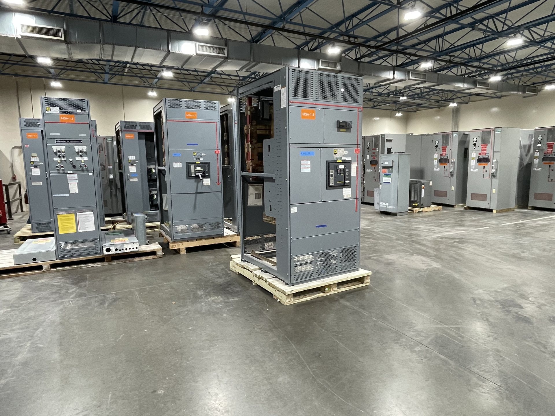
Define the 1600-Amp Retrofit Boundary
Start by identifying exactly what will be replaced or extended: a complete distribution section, a main or feeder compartment, a bus transition, or equipment connected to an existing lineup. Record the equipment function, system voltage, phase and wire arrangement, incoming and outgoing conductor paths, and the limits of the proposed work. A 1600-amp designation describes a current parameter; it does not establish compatibility with the existing assembly.
Provide the existing manufacturer and equipment identification when available, along with nameplate photographs, one-line diagrams, elevations, and the latest relevant revisions. Mark which sections remain, which are removed, and where the new assembly must connect. For an extension, identify the adjoining lineup and intended connection sequence. These details help us assess whether a new configuration is practical without assuming that legacy dimensions or ratings follow a common pattern.
Measure Bus and Connection Interfaces
Measure the bus interface at accessible, de-energized points under the facility’s approved procedures. Document bus width and thickness, number and arrangement of bars per phase, phase spacing, orientation, joint locations, bolt pattern, and available clearance around each connection. Show dimensions from fixed enclosure datums rather than relying on a single overall measurement. Include the neutral and equipment-grounding bus where applicable, and note barriers or supports that constrain access.
Capture enclosure width, depth, height, section boundaries, mounting and anchoring details, door swing, cable-entry area, and required working or service clearances. Record conduit, cable, and busway entry locations, plus obstructions such as structural members and nearby equipment. Photographs should have a scale or accompany dimensioned sketches. If a joint or internal feature cannot be measured safely, identify it as unverified; do not infer a fit from exterior dimensions alone.
Verify Continuous-Current and Thermal Conditions
Confirm the intended continuous-current duty and the rating of every interface in the proposed path, not just the 1600-amp equipment designation. Review the existing assembly nameplate, bus and device documentation, conductor information, ambient conditions, enclosure arrangement, and any known restrictions. The project engineer should determine whether the replacement or extension must preserve an existing rating or meet a different design requirement, and identify the basis for that requirement.
Heat performance can depend on enclosure size, ventilation, adjacent sections, conductor termination limits, device selection, and the physical arrangement of bus. Provide the load profile or project design basis when available, along with details of any planned changes in feeder quantity or loading. We review the requested configuration for quotation; the customer’s responsible engineer must confirm application suitability. Do not treat a matching ampere figure as proof that a retrofit interface or thermal arrangement is acceptable.
Establish Available Fault Duty and Protection
Determine the available short-circuit current at the point of connection and document the study assumptions, source configuration, and relevant upstream protective devices. Identify the required short-circuit rating for the new equipment and any limitations imposed by existing connected sections. A 1600-amp continuous-current rating does not specify fault withstand or interrupting capability, and changing a main or feeder device can affect coordination throughout the distribution system.
Send the current one-line diagram, protective-device schedules, and available coordination or short-circuit study information for review. Note whether the project requires specific trip functions, settings ranges, metering, or communication interfaces. The engineer of record should assess selective coordination and system protection for the actual installation. Applicable standards and any requested listing must be verified for the proposed configuration; UL 891 applies to switchboards and is not a blanket listing for every form of switchgear.
Choose Replacement or Extension Scope
For a replacement, define what must remain connected to the new assembly: feeder count, conductor size and termination style, metering, control wiring, interlocks, and access requirements. State whether the scope includes only new equipment or also new transition components needed to interface with retained equipment. Identify any components that must be reused, but do not assume a retained part is suitable until its condition, ratings, and interface are evaluated by qualified project personnel.
For an extension, provide the existing lineup arrangement and identify the intended electrical and mechanical connection points. Clarify whether the extension must match the existing footprint, door layout, cable direction, and operating access, and whether a transition enclosure or other new interface component is being considered. We manufacture new equipment and new retrofit components to specification; we do not represent a proposed design as compatible until project information has been reviewed.
Coordinate the Outage and Procurement Package
Build the outage plan around the full sequence: isolation, removal, access preparation, placement, connection, inspections, required testing, and return-to-service approval. Identify shutdown windows, affected loads, temporary power responsibilities, access and lifting constraints, and dependencies on other trades. Installation, servicing, testing, and energization require qualified personnel following approved procedures. Confirm who controls the outage and who authorizes each hold point before equipment is released for installation.
For a pricing request, submit the scope boundary, measured interface drawings, one-line diagram, nameplate data, fault-duty basis, device and accessory requirements, and target project milestones. Call out requested American components explicitly; component origin and documentation must be confirmed for each quotation, and this does not establish independent verification or Buy American compliance. Availability, engineering review, applicable standards, test documentation, and lead time are project-specific and must be confirmed before procurement planning is finalized.