Define the Voltage Class and System Conditions
For a 5 kV-class lineup, identify the nominal system voltage and the rated maximum voltage required for the equipment. These are related but not interchangeable values: the system description alone does not establish the equipment rating. Include system frequency, grounding method, operating configuration, and any expected source or transformer arrangements so the proposed design can be reviewed against actual service conditions.
Ask the project engineer to confirm whether the lineup is for incoming service, distribution, motor loads, generator connections, or a combination of functions. Record the number and purpose of sections, bus connections, and any tie or transfer requirements. These details affect the one-line interpretation, breaker selection, and physical arrangement. We confirm engineering and availability for each quotation rather than treating the 5 kV class as a complete design specification.
Specify Insulation and Dielectric Requirements
Insulation requirements depend on the equipment rating, construction, service environment, and applicable project standards. Provide the specified rated maximum voltage and insulation levels where the project documents call them out. If the design basis uses particular clearances, insulation materials, or environmental assumptions, submit those requirements for engineering review instead of inferring them from a nominal system voltage.
Document the intended indoor or outdoor application, ambient conditions, altitude assumptions, contamination concerns, and any special space or environmental constraints. These factors may affect enclosure design and insulation coordination. Identify required standards and documentation in the procurement package, and request confirmation of how they apply to the proposed configuration. Standards applicability and any listing status must be verified for the assembly being quoted; no general claim should be assumed to cover every configuration.
Establish Short-Circuit Duty and Coordination
Short-circuit duty must be based on the available fault current at the switchgear location and the protection-clearing conditions established by the system study. Provide the study basis, including source information, transformer data, and relevant conductor or bus contributions. The required interrupting and withstand capabilities are design inputs, not values that can safely be selected from the voltage class alone.
Coordinate the specified breaker duties with the lineup bus and the protection scheme. Clarify whether the project requires particular momentary, interrupting, or short-time withstand performance, and identify the duration or coordination assumptions where applicable. Submit the current protection study and one-line diagram with the inquiry when available. Final suitability depends on engineering review of the complete duty requirements and the proposed equipment configuration.
Plan Breaker Sections and Compartment Arrangement
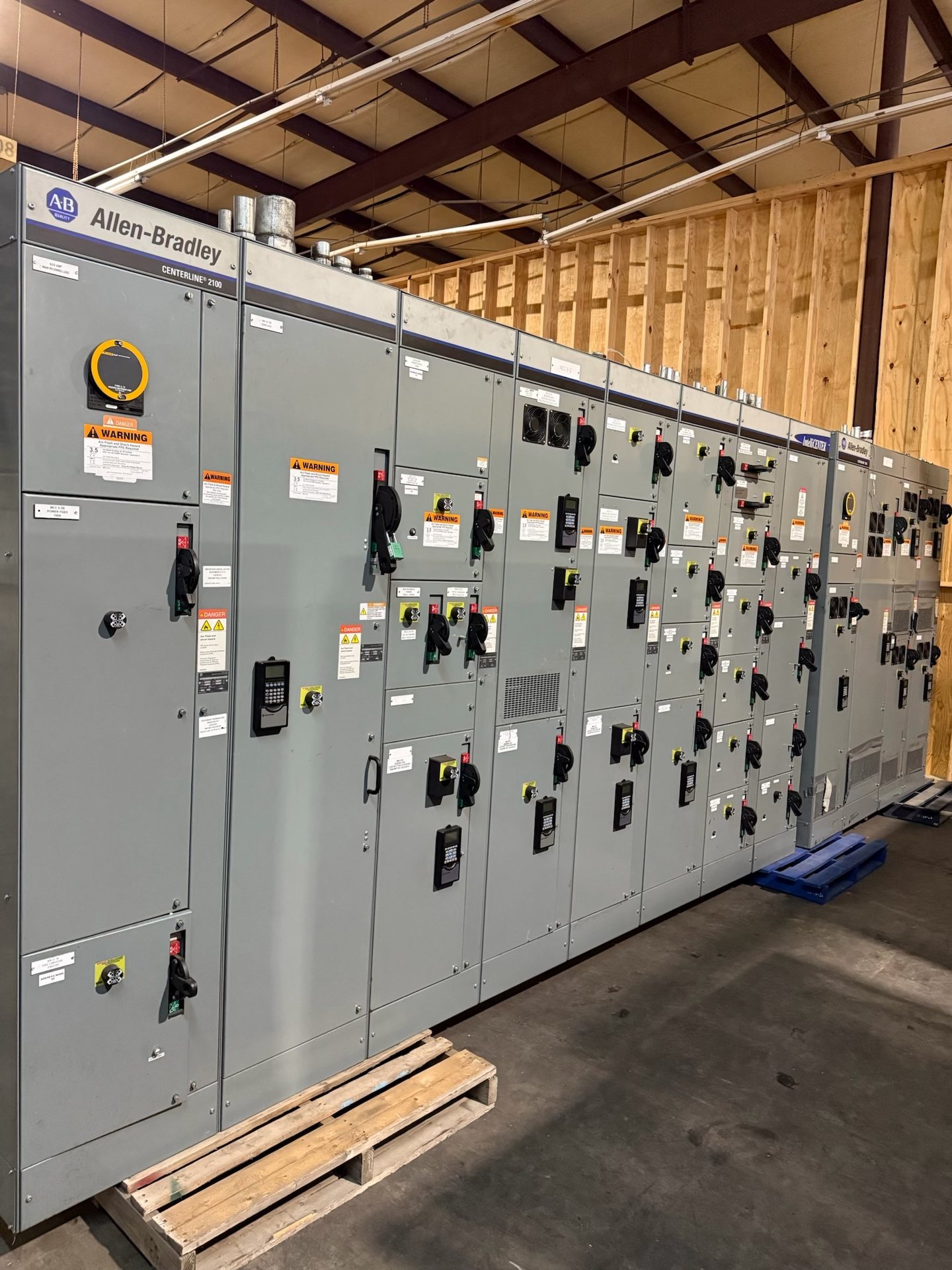
Describe each metal-clad breaker section by function: incoming, feeder, tie, bus connection, or another defined role. State breaker type and operating requirements, including any required control voltage, interlocks, and electrical or mechanical accessories. Provide the one-line diagram and section elevations or dimensional constraints so the lineup can be evaluated as an integrated assembly rather than as a collection of nominally similar cubicles.
Specify the intended compartment arrangement and identify which spaces must accommodate circuit breakers, instrument transformers, control wiring, bus connections, or auxiliary devices. Note cable entry direction, termination space, access restrictions, and any planned future sections. Confirm lineup dimensions and connection interfaces with the installation design. Compartment details and available configurations are subject to project review; do not assume an existing footprint or bus arrangement will accept a different assembly without verification.
Develop Relaying, Controls, and Instrumentation
Define protection functions by circuit and operating purpose, then identify the relay features required by the coordination study. The specification should address sensing inputs, trip and alarm logic, communications expectations, control power, and the intended interface with plant or utility systems. Provide relay settings or a clear statement of who will develop and approve them. A relay model or feature list alone does not establish a complete, coordinated protection design.
List required current and voltage transformers, metering, indication, and auxiliary contacts, including ratios and accuracy requirements where the design documents specify them. Clarify wiring interfaces, terminal requirements, and whether control schematics or connection drawings are needed for review. We can evaluate new equipment and new retrofit components against the submitted requirements, but compatibility with existing relays, wiring, and breaker mechanisms must be confirmed for the particular gear.
Scope New Equipment, Retrofit Components, and Submittals
For a new lineup, request a quotation using the project one-line, equipment schedule, fault-duty information, relay requirements, and any applicable dimensional drawings. Identify required submittals, such as general arrangement drawings, elementary diagrams, wiring information, and component data. State the governing project standards and approval process. We manufacture and supply new equipment; availability, engineering, component origin, lead time, and documentation are confirmed individually during quotation and review.
For retrofit work, specify that the requirement is for new replacement components and provide the existing manufacturer, switchgear identification, breaker and cell information, nameplate data, photographs, and interface drawings when available. Include bus, secondary disconnect, control voltage, and mechanical interlock details. Those records help assess fit and function, but do not establish interchangeability by themselves. Installation, servicing, testing, and energization must be performed by qualified personnel under approved procedures.