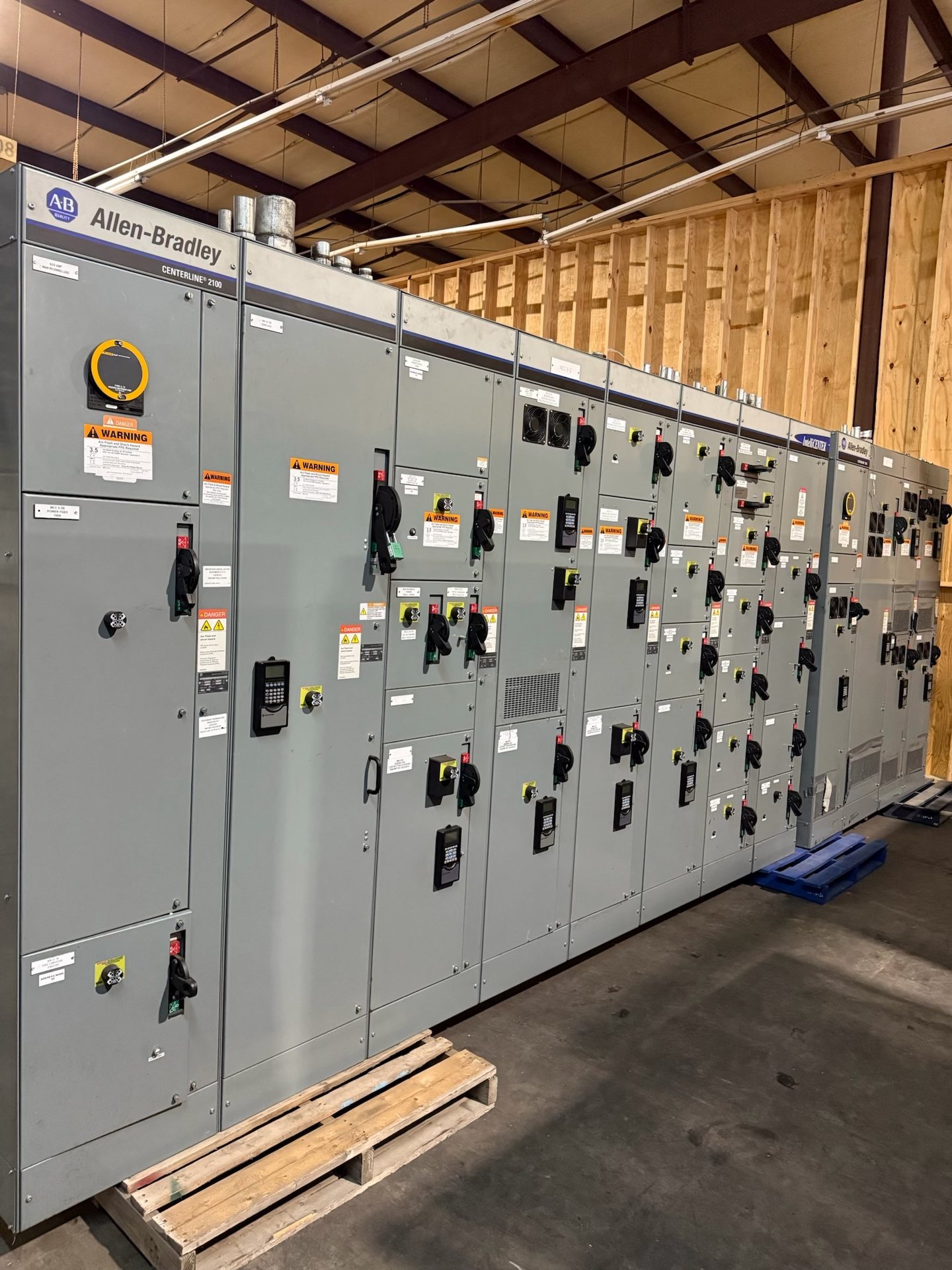
Set the voltage class and system configuration
Start with the nominal system voltage and the highest voltage for which the equipment must be designed, rather than relying on a general description such as medium voltage. Confirm whether the project is new construction, a replacement lineup, or an extension to existing gear, and document the grounding method, source arrangement, and expected operating conditions. These details help establish a suitable equipment configuration for an Austin-area project without assuming a particular utility standard.
For a pricing and engineering review, provide one-line diagrams, the stated system voltage, bus arrangement, source and load information, and any interface constraints. Identify whether incoming and outgoing circuits are in the same lineup, whether bus ties are required, and how the equipment connects to transformers or other switchgear. Existing drawings and nameplate information are particularly useful for replacement work, but field conditions should be verified by the project team.
Choose the breaker and switching arrangement
The switching scheme should reflect how the installation is operated and maintained. Specify whether feeder and main circuits require circuit breakers, whether a bus-tie or transfer arrangement is part of the design, and whether isolation or grounding provisions are needed. For each circuit, clarify its function, the preferred operating sequence, and any interlocking requirements. A one-line diagram with normal and alternate operating states makes these decisions easier to review than a generic equipment description.
For replacement or expansion, identify the existing manufacturer and model where known, cell dimensions, bus connections, control voltage, and the intended scope of work. New retrofit components must be selected against verified equipment details; apparent similarities do not establish mechanical or electrical compatibility. Switchgear Builders Texas supplies new equipment and new retrofit components. Confirm the required interfaces and replacement boundaries before requesting pricing so the scope does not omit controls, accessories, or bus transitions.
Define protection relay interfaces
Relay requirements affect both protection design and the switchgear control scheme. Identify which protective functions and trip logic the project requires, what instrument-transformer inputs are available, and how alarms, status points, and breaker control signals must interface with the facility system. If a project specifies an existing relay platform or communications protocol, provide the applicable requirements and point list. The final relay and wiring arrangement must be reviewed against the equipment configuration and the protection engineer’s design.
Useful quotation documents include elementary and connection diagrams, control schematics, relay setting responsibilities, and a schedule of customer-supplied signals or devices. Clarify who furnishes relays, current and voltage transformers, metering, and communications equipment, and whether control wiring must terminate at defined field interfaces. Do not assume that a relay is included or that a particular protocol, point count, or setting is standard. Confirm scope, component origin, and available documentation for each quotation.
Coordinate cable terminations and access
Cable entry and termination space can determine the practical lineup layout. State whether incoming and outgoing cables approach from above or below, the cable type and conductor arrangement, and the termination method required by the project design. Provide conductor size and quantity, shielding or grounding details, and any limits on bend space or access. These inputs help evaluate compartment space, stress-control interfaces, and safe working clearances without assuming cable dimensions from the nominal voltage alone.
For retrofit work, document the existing cable route, termination locations, enclosure constraints, and any transition between the old and new equipment. Confirm who supplies termination kits and field connectors, which components must match the cable specification, and what information the installer needs before arriving at the site. Drawings should identify entry points and connection responsibilities. Installation and termination work must be performed by qualified personnel under approved project procedures.
Match insulation and fault-duty requirements
Insulation selection and interrupting capability must correspond to the actual system and application. Provide the specified voltage class, insulation approach, environmental conditions, and any project requirements for indoor or outdoor service. For fault duty, submit available short-circuit information, required interrupting performance, and the expected duration or coordination basis where applicable. Equipment suitability cannot be inferred from voltage alone; the design review needs the system study and the project’s governing specifications.
When existing studies are preliminary or unavailable, identify that status in the request rather than substituting an assumed rating. The engineer of record should establish the applicable duty and verify coordination with upstream and downstream protection. Also disclose unusual ambient, altitude, contamination, or space constraints that may affect the selected configuration. Applicable standards and any listing requirements should be verified for the specific assembly; UL 891 applies to switchboards and is not a blanket standard for medium-voltage switchgear.
Prepare a complete Austin project request
A clear request connects the technical design to purchasing and schedule decisions. Include the one-line diagram, equipment and circuit schedule, required drawings, interface responsibilities, requested documentation, and delivery destination in Austin, Texas. Note whether the project has a required submittal sequence, site access limitations, or a planned outage window. These details support a project-specific review, but they do not establish a guaranteed lead time or delivery date; timing is subject to configuration, engineering, and quotation review.
Before release, compare the quoted scope with the project specification and approved drawings. Confirm voltage and fault-duty basis, breaker and bus arrangement, relay and control interfaces, cable termination provisions, component-origin requirements, and exclusions. Customers may specify American components; any applicable domestic-content or procurement compliance must be established and documented for the particular order rather than assumed. Request pricing for new equipment or new retrofit components and verify listing, standards, and test-document requirements against the final configuration.