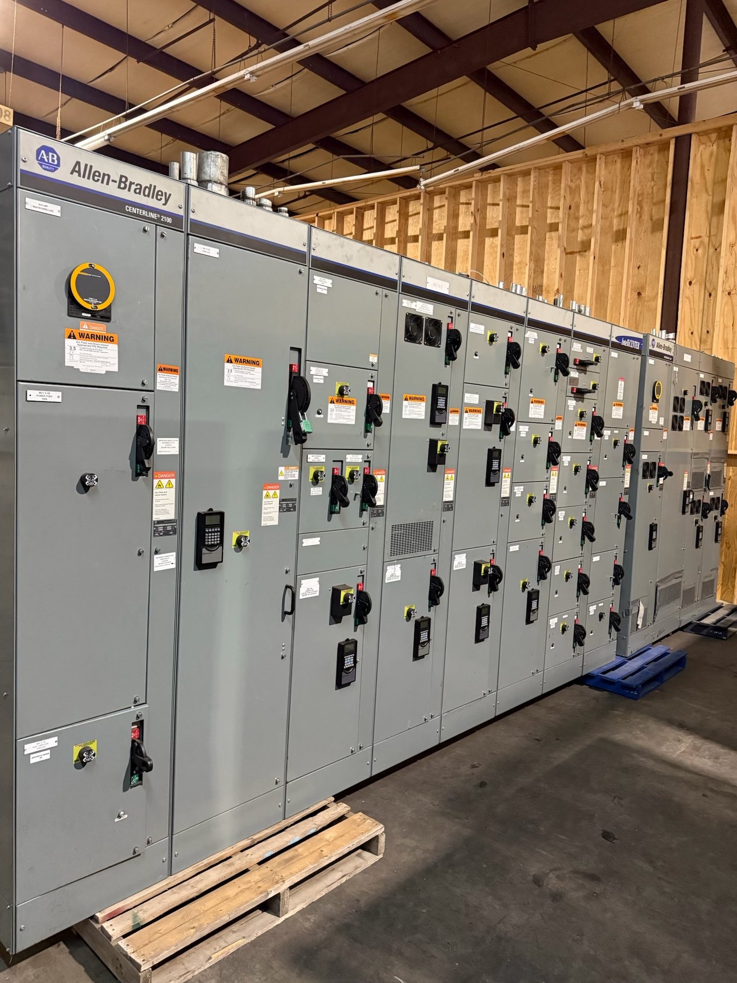
Coordinate the service entrance with the utility
For a Corpus Christi project, begin with the serving utility’s current service requirements rather than assuming a standard arrangement will be accepted. Confirm the service point, available fault-current information, metering method, approved compartment arrangement, access clearances, and any utility-controlled equipment. These details affect the switchboard’s dimensions and internal layout, so they should be resolved with the utility and electrical engineer before the equipment configuration is finalized.
Include the utility’s written requirements, service drawings, and review comments in the quotation package. Identify who will submit drawings for approval and whether utility acceptance is required before fabrication. Also clarify the project schedule for utility review, because an equipment release that precedes a required design decision can create avoidable changes. We can evaluate the requested configuration against the documents supplied; utility approval remains a separate project coordination responsibility.
Define service disconnects and compartment arrangement
Specify the service disconnect arrangement in terms of the actual one-line diagram and code requirements for the project. State the number and type of disconnects, the loads or downstream sections each serves, and any required main or distribution configuration. Where multiple disconnects are proposed, confirm their grouping, identification, and operating access with the design professional and authority having jurisdiction. The requested arrangement should be explicit rather than inferred from a broad equipment description.
A service entrance switchboard must also provide space for the intended devices and conductor terminations while preserving required barriers and working access. Submit the one-line, load schedule, equipment schedule, and relevant riser or room plans. Note any future sections, spare provisions, or unusual termination needs. These choices influence the structure and should be addressed during design review, not left to field modification after the switchboard arrives.
Resolve metering requirements before layout
Metering compartments are utility- and application-dependent. Confirm whether the project requires a utility meter, instrument transformers, test provisions, or a particular compartment position, and identify which party supplies and installs each component. The metering method can determine the location and dimensions of barriers, windows, access doors, and wiring spaces. Send the utility’s metering specifications with the project documents so the proposed switchboard can be reviewed against the intended service arrangement.
Clarify access, sealing, and ownership boundaries for metering equipment, including any restrictions on who may open or service a compartment. Provide the meter or instrument-transformer details only when they have been confirmed by the responsible parties. If those details are pending, identify them as open design items in the quotation review. Do not assume a metering space is acceptable simply because it fits physically; utility acceptance and applicable project requirements must be verified.
Plan incoming conductors and termination space
The incoming conductor route is a defining switchboard constraint. Provide the planned entry direction, raceway locations, conductor material and quantity, insulation and temperature assumptions, and termination requirements as established by the electrical design. Include cable or busway approach details and available bending space where relevant. These inputs help determine whether the service section can accommodate the proposed connections without conflict with barriers, metering compartments, or adjacent distribution equipment.
Confirm the point of entry and termination arrangement against the service room plan and the utility’s requirements. Consider how raceways will align with the equipment, whether conductors approach from above or below, and what access is needed to make terminations. Changes to entry locations or conductor assumptions can require equipment revisions. Installation and connection work must be performed by qualified personnel using approved project procedures; field conditions should be checked against the released drawings.
Document grounding and bonding requirements
Grounding and bonding details should be coordinated with the service configuration, system grounding method, and applicable electrical code requirements. The design package should identify the intended grounding electrode conductor connection, equipment grounding and bonding provisions, neutral treatment, and any required bonding points. Do not assume the neutral-to-ground relationship from the equipment name alone; it depends on the service arrangement and must be established by the responsible electrical designer.
Provide the grounding notes, one-line diagram, and relevant specifications with the quotation request, and flag any requirements for a particular termination location or conductor routing. Review how grounding and bonding provisions interact with metering barriers and incoming conductor space. Final acceptance depends on the approved design and applicable authority requirements. Installation, inspection, and energization should follow approved procedures and be handled by qualified personnel.
Build a complete quotation and retrofit scope
For pricing, submit the project location, requested service configuration, one-line diagram, utility requirements, metering details, conductor-entry plan, grounding notes, and available room dimensions. Include the required delivery window and identify the drawing review and approval milestones. We manufacture new equipment to specification; availability, engineering review, lead time, component origin, and test documentation are confirmed for each quotation. A complete package makes open decisions visible and supports a more meaningful scope review.
For retrofit work, specify new switchboard equipment or new replacement components only, and describe the existing equipment interface in detail. Provide manufacturer and model information when known, dimensions, connection points, photographs or drawings, and the intended scope boundary. Existing conditions must be verified by the project team before ordering. We do not assume that a new component will fit or perform in an existing assembly without engineering review; configuration, applicable standards, and any listing requirements must be confirmed for the specific design.