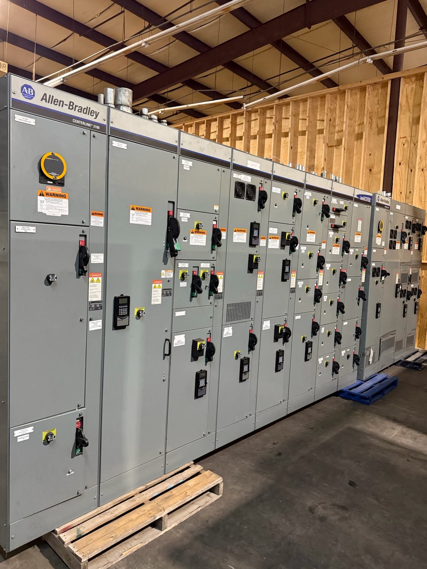
Plan the Dallas Retrofit Around the Existing Installation
A retrofit is not simply a replacement order: the new assembly or components must fit the existing electrical and physical arrangement while meeting the project’s operating requirements. Begin by identifying the equipment type, manufacturer and model if known, lineup arrangement, connected systems, and the specific sections or devices in scope. For Dallas facilities, clarify whether the work is a component renewal, a lineup extension, or replacement of an existing assembly.
Useful survey records include equipment nameplates, approved drawings, one-line diagrams, control schematics, dimensions, photographs, and available maintenance or modification history. Note missing, conflicting, or outdated information rather than assuming the drawings reflect field conditions. We use the information supplied for engineering review and quotation; a project team must confirm site conditions and whether additional field verification is needed before releasing equipment for manufacture.
Verify Replacement Compatibility Before Ordering
Physical fit and electrical function both matter. Compare enclosure and section dimensions, mounting and connection interfaces, cable entry and exit arrangements, barriers, access clearances, and the location of control wiring. For a device replacement, document its function, interface, control voltage, auxiliary contacts, interlocks, and connection details. A component that appears similar may not be compatible with the installed assembly or its intended operating sequence.
Identify the exact scope of replacement: device only, device with related control components, a section, or a complete switchboard or switchgear lineup. Provide available manufacturer documentation and identify any field changes that affect interfaces. We manufacture new equipment and new retrofit components to specification. Final compatibility, required adaptations, component availability, and applicable standards must be confirmed for the quoted configuration.
Reconcile Bus and Fault Ratings
The replacement design must account for the existing bus arrangement and the electrical duty established for the installation. Gather the bus configuration and rating information available from equipment labels and drawings, along with system voltage, current requirements, and the available fault-current information used by the project engineer. Note whether the work changes the lineup, feeder arrangement, connected load, or upstream protective equipment, since these can affect design review.
Do not assume that a new section or component inherits the ratings of adjacent equipment merely because it fits the same space. Confirm how the proposed equipment interfaces with the existing bus and how the project establishes the required short-circuit or withstand performance. Ratings and design suitability are configuration-specific and require review against project documentation. Any listing and applicable standards should likewise be verified for the actual assembly; UL 891 applies to switchboards, not as a blanket claim for all switchgear.
Build an Outage Sequence That Fits Operations
A modernization plan should state what must be de-energized, which loads are affected, and whether the work can be divided into planned stages. Coordinate the proposed sequence with facility operations, the electrical contractor, the project engineer, and any parties responsible for upstream and downstream equipment. Establish which existing sections remain in service during each stage and whether temporary operating arrangements require separate engineering and approval.
Tie procurement milestones to the outage plan without treating a preliminary schedule as a delivery commitment. Confirm when approved drawings and interface information are needed, what review cycles apply, and when the site can accept equipment. Lead time is subject to project review and confirmation in the quotation. Installation, testing, and energization must be performed by qualified personnel under approved procedures and the facility’s safety and outage requirements.
Coordinate Field Installation and Interfaces
Before equipment release, assign responsibility for field measurements, removal of existing equipment, preparation of the installation area, conduit and cable interfaces, grounding connections, and final integration. Record access routes, handling constraints, room dimensions, working clearances, and any limits on bringing equipment into the electrical room. Confirm who resolves field discrepancies and who approves changes that affect the design or installation scope.
For a replacement lineup or section, document transition points between new and retained equipment, including bus connections, control wiring, protective-device interfaces, and identification requirements. New components may require installation details that differ from the equipment being replaced, so the contractor should compare approved drawings with verified field conditions before work begins. We can review defined interface information for the quoted scope, while site execution remains coordinated by the project’s qualified installation team.
Prepare a Complete Request for Pricing
A useful pricing request identifies the Dallas project site, equipment scope, application, required system parameters, and desired procurement milestones. Include the latest one-line diagram, equipment schedules, relevant existing drawings, nameplate data, survey dimensions, and known interface conditions. State which information is preliminary and which has been verified. Also identify the requested documentation and any project-specific submittal, review, or approval requirements.
Specify whether the request is for new replacement equipment, new retrofit components, or both, and describe the boundary between the new work and retained equipment. Ask us to confirm configuration, component origin, applicable standards, documentation, availability, and lead time for the quotation rather than relying on assumptions. We serve Dallas from the United States and manufacture to specification; project details determine engineering scope and whether the proposed replacement is suitable.