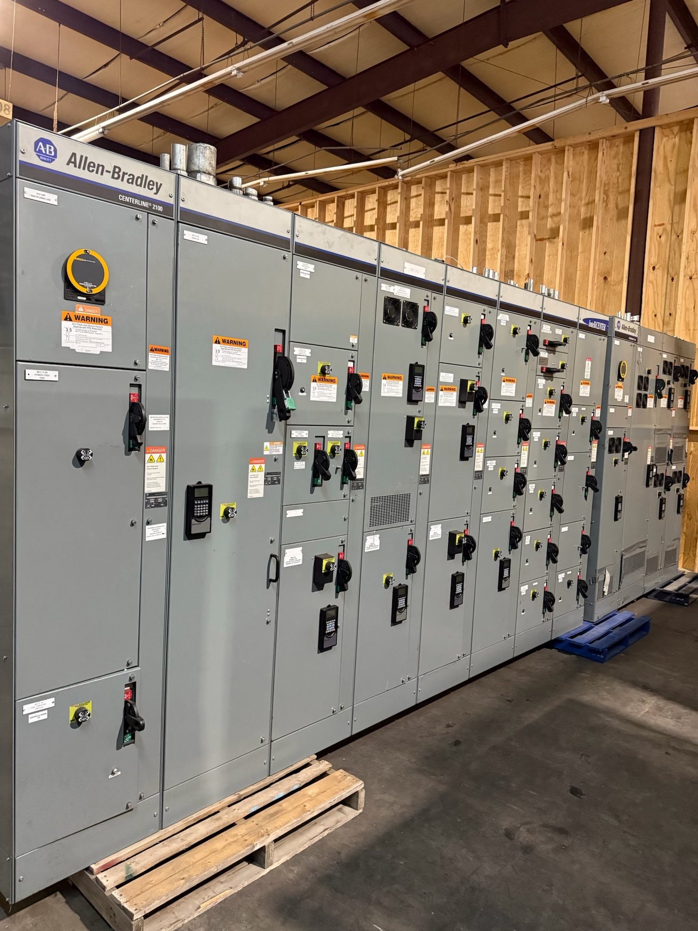
Choose a feeder breaker or fused-switch arrangement
Start with the function and protection requirements of each outgoing feeder. A circuit breaker arrangement and a fused-switch arrangement involve different device selections, operating characteristics, maintenance considerations, and coordination with downstream equipment. Provide the required device type for each circuit, along with its design ratings and any project-specific trip, fuse, or accessory requirements. Do not assume that one arrangement is interchangeable with another without engineering review.
A feeder schedule is a practical basis for defining the distribution section. For each outgoing circuit, identify its destination, protective-device preference, design current, conductor information, and whether spare ways are required. Also note any common operating or coordination requirements that affect several feeders. We review those inputs against the proposed assembly configuration; device availability, ratings, and applicable standards must be confirmed for each quotation.
Plan outgoing conductor space before setting the layout
Conductor termination space can influence the size and arrangement of a feeder section as much as the number of devices. Document whether conductors enter from the top or bottom, their material and quantity, termination constraints, and the routing space needed beyond the switchboard. Include the expected conduit locations and any site restrictions that could affect access to feeder terminals or cable bending and routing.
Ask the project team to confirm conductor sizes and quantities with the electrical design before the equipment layout is finalized. Note whether separate compartments, barriers, or a particular wireway arrangement are required, and identify any field conditions that limit section width or depth. These details help us review a buildable configuration instead of relying on a circuit count that leaves termination needs unresolved.
Make circuit identification useful in the field
Feeder names should tell installers and future operators what each device supplies, not merely repeat a panel position or sequence number. Provide the preferred circuit description, destination designation, source reference, and any required labeling convention. If identification must match drawings, equipment schedules, or an owner’s naming system, submit those references with the quotation request and identify which information is final.
Resolve the naming approach before fabrication where possible. A feeder schedule can distinguish active circuits, designated spares, and spaces reserved for future use, reducing the risk that an open position is mistaken for an available connection. Tell us whether labels must follow specified text, numbering, or drawing references. Final label content and documentation requirements should be reviewed with the approved project submittals.
Allocate loads across the distribution section
A feeder list should show how the connected loads are grouped and how their design demand informs each outgoing circuit. Provide load schedules or the relevant design values, identify continuous or special loads where applicable, and explain any planned operating patterns that affect allocation. The electrical engineer remains responsible for the system design; the switchboard configuration should follow the approved one-line diagram and project requirements.
Review the proposed allocation for intended future changes as well as present destinations. If spare capacity or reserved feeder positions are requested, state whether they mean an unused device position, a provision for a future device, or another defined arrangement. Those terms can describe different equipment requirements. Confirm the intended meaning, feeder ratings, and any associated space or connection provisions before requesting pricing.
Coordinate feeder protection and system interfaces
Feeder devices need to fit the electrical system and the downstream equipment they supply. Include the project one-line diagram, available system information, specified interrupting or withstand requirements, and coordination criteria relevant to the distribution section. Identify any interface constraints involving the incoming section, bus arrangement, grounding scheme, or adjacent equipment so the feeder design can be reviewed in context.
Do not select a breaker or fuse solely by matching a downstream load label. Protection settings, device characteristics, and coordination depend on the engineered system and must be established by qualified professionals. We use the submitted requirements to scope a new assembly or review new retrofit components for a defined existing configuration. Ratings, component availability, and documentation are confirmed during quotation and engineering review.
Specify new equipment and retrofit components clearly
For a new feeder distribution switchboard, provide the approved or current one-line diagram, feeder schedule, site conductor-entry information, applicable project specifications, and requested submittal documents. State the intended installation environment and any constraints on section arrangement or access. We manufacture new equipment to specification and can review short lead-time possibilities after the project scope and component requirements have been evaluated.
For an existing installation, identify any requested new retrofit components by switchboard manufacturer, model or type, existing device details, available drawings, and clear photographs where appropriate. Explain the intended feeder function and the configuration the component must fit. Compatibility, engineering suitability, component origin, and lead time are project-specific and require confirmation. UL 891 applies to switchboards; listing and applicable standards should be verified for the proposed configuration.