Coordinate the Houston Service Entrance With the Utility
Before the switchboard design is finalized, confirm the serving utility’s current requirements for the project address and service type. Ask which party provides and installs service conductors, where the service point and metering equipment must be located, and whether the utility requires a particular compartment arrangement, access provision, or connection method. Requirements can vary by service and project, so assumptions from another site should not substitute for written coordination.
For a quotation, provide the utility service requirements or correspondence alongside the one-line diagram and project specifications. Identify the service voltage and phase, proposed service capacity, transformer or service source details when known, and any utility review milestones. These inputs help establish a buildable configuration and flag open decisions before procurement. Final acceptance remains subject to the utility’s requirements and review of the specific installation.
Define Service Disconnects and Protection
The service disconnect arrangement determines how the building’s service is isolated and how protection is coordinated with downstream distribution. Specify the number and type of service disconnects, the intended distribution sections, and any project requirements for overcurrent protection. The engineer should document the system grounding method and coordination assumptions, including how the service equipment relates to downstream panels, feeders, and emergency or standby sources where applicable.
Provide available fault-current information at the service equipment, or identify who will establish it, so the design team can evaluate equipment ratings and protective-device coordination. Also clarify enclosure and access constraints, control or interlock requirements, and whether future distribution provisions are needed. We review these parameters against the proposed assembly; ratings, device selections, and configuration must be confirmed for each project rather than inferred from a general product description.
Resolve Metering Compartments Before Layout
Metering is often governed by utility rules as well as the owner’s operational needs. Confirm whether the project calls for utility-owned or customer-owned metering equipment, the required compartment location, and any separation, sealing, access, or instrument-transformer provisions. Ask the utility to identify acceptable metering arrangements and dimensions before the switchboard footprint is fixed. This is especially important where electrical rooms are constrained or the service entrance shares space with other distribution equipment.
The submittal package should identify the metering scheme and show how its compartment relates to incoming service conductors, service disconnects, barriers, and cable access. Include utility comments or approved drawings when available, and make unresolved requirements explicit. Metering components and compartment details depend on the project and utility review; they should not be assumed standard or treated as approved solely because they appear on a preliminary one-line.
Size and Route Incoming Conductors
Incoming conductor details affect the switchboard’s physical arrangement as well as its electrical design. Establish conductor material, quantity, size, insulation, and termination requirements from the engineered documents, and confirm whether conductors enter from above or below. Provide the expected conduit locations, entry area, bending and pulling constraints, and any transition from utility conductors to customer conductors. These details help the design team assess landing space and access within the proposed enclosure.
Where the utility has not yet finalized conductor information, identify the responsible party and the point at which the data will be confirmed. Avoid relying on assumed conductor dimensions when coordinating the electrical-room plan, conduits, or equipment clearances. The quotation and drawing review should resolve the connection method, lug or termination provisions, and any required barriers. Final conductor selection and installation must follow the engineered design and applicable requirements.
Document Grounding and Bonding Requirements
A service entrance design needs a clear grounding and bonding plan, not just a grounding terminal callout. Provide the project’s grounding electrode system details and identify where the service neutral, equipment grounding paths, and bonding connections are intended to terminate. The electrical engineer should address the system configuration and applicable code requirements, including the relationship between service equipment and downstream equipment. Utility rules may also affect how the service connection and metering arrangement are configured.
For design review, supply grounding notes, relevant one-line details, and any project-specific bonding requirements. Confirm whether the requested assembly must accommodate particular conductor entry or termination locations, and coordinate those locations with the enclosure layout. Grounding and bonding provisions are configuration-specific and should be checked against the approved design. Installation, inspection, and energization require qualified personnel working under approved procedures; this page is not field-work guidance.
Scope New Equipment and Retrofit Components
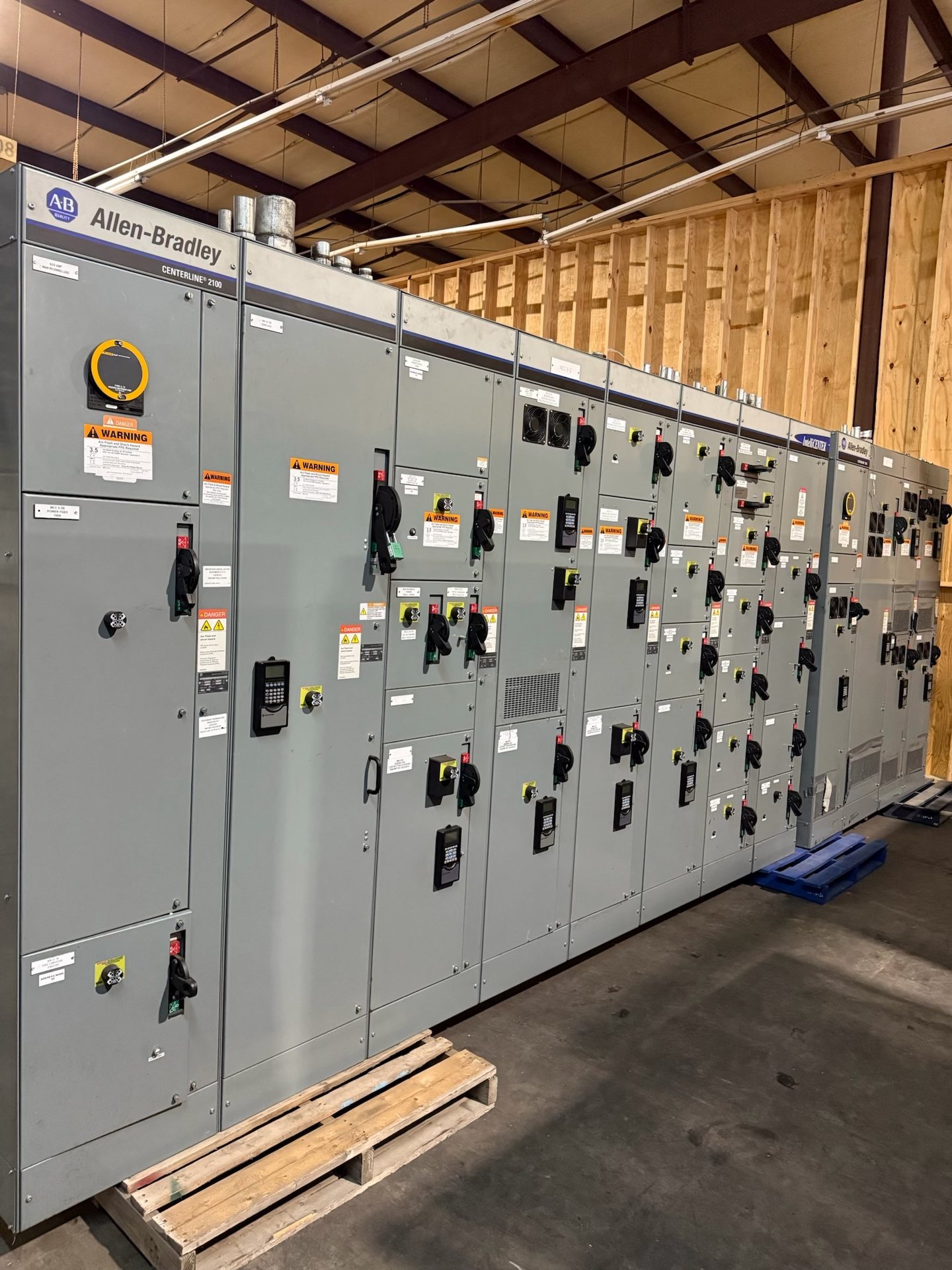
We supply new service entrance switchboards and new retrofit components for Houston-area projects. For a replacement or retrofit scope, document the existing equipment manufacturer and identification data, available drawings, enclosure dimensions, bus and connection details, and the components to be replaced. Photographs can supplement records but do not establish compatibility. The engineering review must determine whether the requested new components can be configured for the existing equipment and intended application.
For new assemblies, include the specification, one-line diagram, load and service data, utility requirements, metering criteria, conductor information, grounding plan, and installation constraints with a pricing request. Identify requested American components and any documentation needed for review; component origin and supporting documentation must be confirmed for the quotation, and no blanket domestic-content certification is implied. UL 891 applies to switchboards; listing and applicable standards must be verified for the exact configuration.