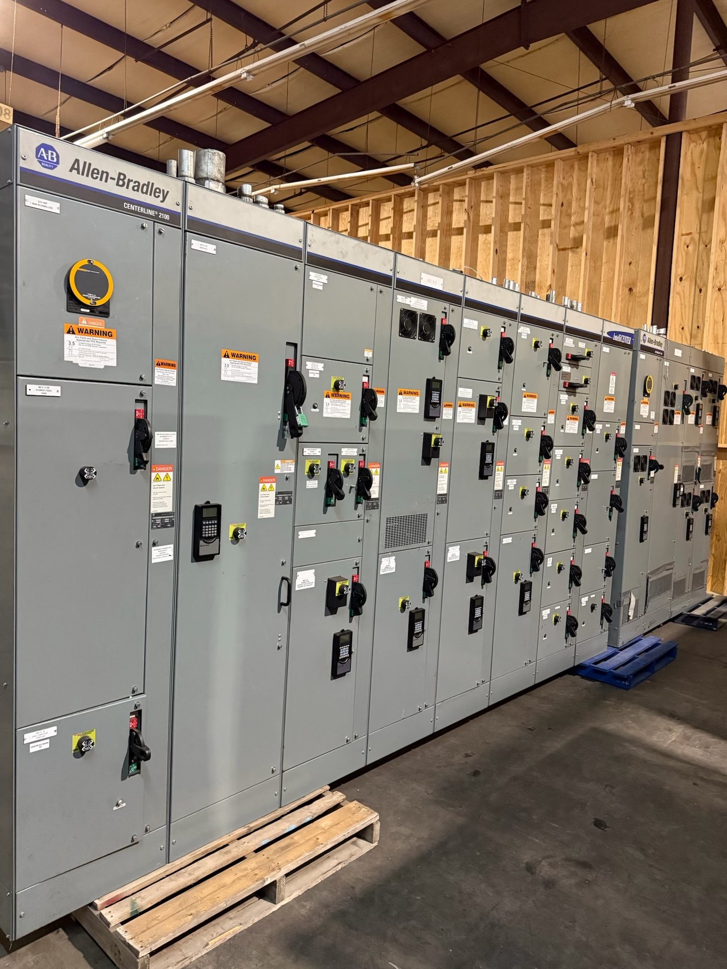
Scope a Waco MCC Around the Motor Schedule
A motor schedule is the foundation for defining each MCC unit. For every load, provide the motor nameplate information available, horsepower, voltage and phase, full-load current, starting method, and whether the motor is continuous or intermittent duty. Also identify the driven equipment, operating location, and any process constraints. These details help distinguish a straightforward across-the-line starter from a load needing reduced-voltage starting or a VFD.
The schedule should also capture how each motor is commanded and monitored: local controls, remote start/stop, permissives, alarms, interlocks, and required status points. Note which signals belong to the facility control system and who supplies field devices and cabling. For Waco projects with phased construction, mark future loads separately from present requirements so the initial lineup can be evaluated for practical expansion without treating unconfirmed loads as final design inputs.
Choose Starters and Overloads for the Actual Load
Starter selection depends on more than motor horsepower. Confirm the system voltage, motor full-load current, starting frequency, load inertia, acceleration requirements, and available fault-current information. Across-the-line starting may suit some loads, while high inrush, voltage-drop limits, or process requirements can call for another approach. The engineer of record should establish the design basis and protection coordination; provide those criteria with the request for pricing rather than relying on a generic starter assumption.
Overload selection should reflect the motor’s nameplate and applicable project requirements, including the specified protection class, reset behavior, and coordination with upstream protective devices. Clarify whether operators need manual or automatic reset and whether overload trip indication must reach a PLC or supervisory system. We build to the approved specification; final device selection and settings must be confirmed for the actual motor and application, not inferred from a typical unit description.
Define VFD Interfaces Before Ordering
For each VFD-driven motor, identify whether drives are to be furnished within the MCC lineup or provided separately, and state the required drive and bypass arrangement. Specify the motor and application data, speed range, control mode, acceleration and deceleration needs, and any process constraints. Also document the intended power and control boundaries between the MCC, drive, motor, and facility systems so the equipment arrangement does not leave interface responsibilities unresolved.
List the control and feedback points expected at the MCC or control-system interface, such as run command, speed reference, running status, fault, and permissive signals. Identify whether communications are required and name the project-approved protocol and network responsibilities. Drive selection, enclosure and thermal considerations, filtering, and bypass details depend on the design and installation environment; they should be resolved during engineering review rather than assumed from the word “VFD.”
Coordinate Control Wiring and Field Signals
A point-to-point control narrative reduces ambiguity between MCC units and field equipment. Provide control schematics or a sequence of operation that defines starts, stops, local/remote selection, permissives, trips, and reset logic. Identify whether control power is furnished in the lineup or comes from an external source, and document voltage and grounding requirements. For each field connection, establish terminal expectations and distinguish factory wiring from wiring completed by the installing contractor.
Control wiring also needs a clear interface with PLCs, distributed I/O, and building or process networks. Supply the required I/O list, alarm descriptions, signal types, communication requirements, and any segregation or shielding criteria in the project documents. Confirm who provides interposing relays, field junctions, network components, and final programming. Installation, servicing, testing, and energization must be performed by qualified personnel under approved project procedures.
Plan Lineup Arrangement and Future Expansion
Expansion planning begins with the anticipated load list, not simply an empty space request. Identify likely future motors, their estimated electrical and control requirements, and the stage at which they may be installed. The design team can then evaluate whether spare unit provisions, additional sections, bus capacity, feeder arrangements, or control-system capacity are appropriate. None should be presumed available without reviewing the proposed lineup and project design conditions.
For a Waco project with later construction phases, provide the available room dimensions, access and handling constraints, incoming and outgoing cable approach, and any restrictions on lineup location. These affect section arrangement and practical addition strategies. Ask the quotation to distinguish presently furnished equipment from future provisions and identify what must be verified before an expansion. This gives purchasing and engineering teams a clearer basis for comparing scope without treating a future addition as guaranteed compatible.
Prepare a Complete RFQ and Retrofit Scope
A useful request for pricing includes the motor schedule, one-line diagram, MCC layout or lineup requirements, control schematics, system voltage, available fault-current data, and applicable project specifications. Include the intended application and operating environment, required communications, incoming power arrangement, and any stated standards or listing requirements. Identify the project schedule and delivery destination in Waco so lead time and shipping considerations can be reviewed for the actual configuration.
When replacing equipment in an existing lineup, provide identification and dimensions for the affected section, available drawings, connection details, and the existing control and power interfaces. We supply new MCC equipment and new retrofit components only; do not assume that a new component will fit or coordinate with existing equipment until the configuration is reviewed. Availability, engineering, component origin, lead time, and test documentation are confirmed for each quotation. Any applicable listing and standards must also be verified for the specific assembly.