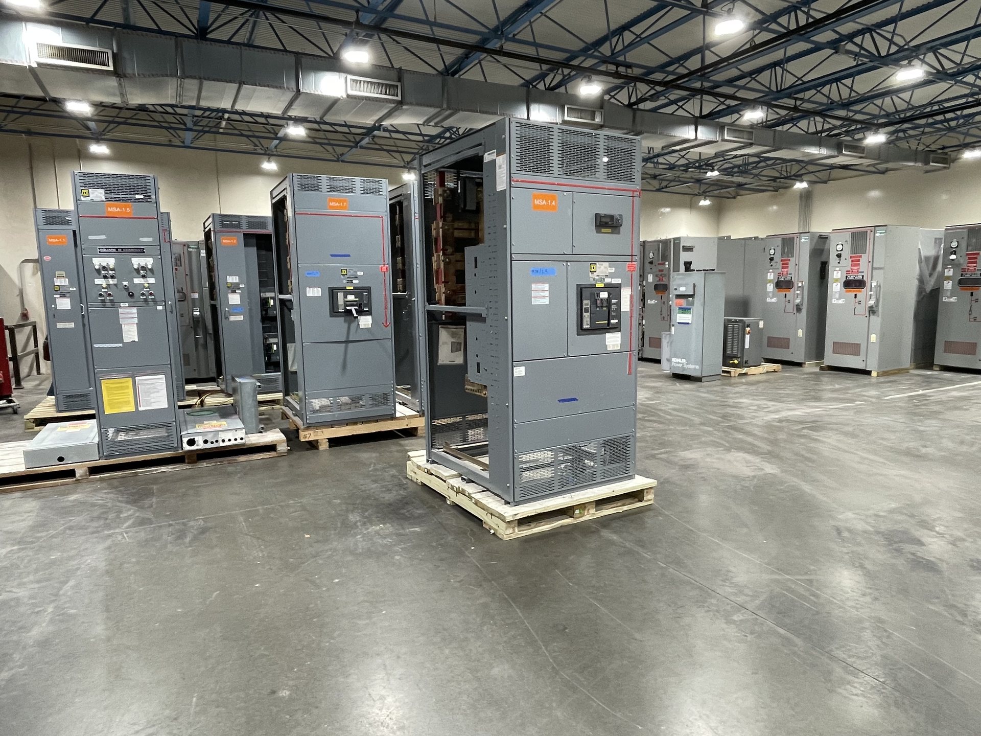
Plan the 1600-Amp Section Layout
Start with the function and sequence of each section: incoming service or source, metering and controls where required, distribution, and outgoing feeders. For a 1600-amp lineup, the arrangement affects cable entry, device access, bus transitions, and the space needed for future circuits. Identify the intended line-up direction and any required connection to existing equipment so the proposed assembly can be reviewed against the actual installation.
Provide the one-line diagram and available elevation or room layout, along with the number and type of feeders, source arrangement, and preferred cable entry points. Note obstructions, working-space constraints, and whether the switchboard must align with other equipment. These details let us evaluate section grouping and enclosure configuration early; dimensions, clearances, and final layout must be confirmed for the project rather than inferred from the 1600-amp designation.
Coordinate Main and Feeder Protection
Specify the main protective device and each feeder by function, rating, and required trip or fuse characteristics. The design review should account for the connected loads, conductor protection, available fault current, and coordination requirements established by the project engineer. A 1600-amp bus rating does not, by itself, determine the main-device rating or the appropriate feeder-device selection.
Document the protection scheme, including any selective-coordination criteria, ground-fault protection requirements, metering, and control interfaces that apply. Identify whether the main is required to be a circuit breaker or another specified device, and provide relevant settings or coordination study inputs when available. Final device selection and configuration depend on engineering review, component availability, and the applicable project requirements.
Define Bus Capacity and Connections
Treat 1600 amps as a design parameter to be verified for the complete assembly, including the main bus, feeder sections, and any transition or distribution sections. Submit the system voltage, phase and wire arrangement, source information, load profile, and anticipated continuous loading. If future growth is part of the scope, state the intended spare capacity or additional feeder provisions instead of relying on an assumed allowance.
Bus material, configuration, and connection details should be addressed in the specification and confirmed during quotation review. Identify any requirements for neutral bus, equipment grounding bus, bus extension, or connections to adjacent equipment. The overall design must be suitable for the specified application and conditions; bus ampacity and configuration cannot be established from the nominal 1600-amp rating alone.
Specify Terminations and Cable Entry
Termination planning is central to a practical 1600-amp switchboard layout. For each incoming and outgoing circuit, provide conductor material, conductor size and quantity, cable or busway connection method, and top or bottom entry preference. Include lug requirements where known and identify any transition hardware or existing connection points that the new assembly must accommodate.
Confirm available routing space, bend-space constraints, conduit locations, and the relationship between cable entry and the selected main and feeder devices. These details affect section dimensions and internal arrangement. For a retrofit, provide verified field measurements and existing-equipment connection information; do not assume a new switchboard or component will fit based only on the existing ampere rating or a general equipment description.
Establish the Short-Circuit Rating
The required short-circuit rating is project-specific and must be evaluated against the available fault current at the switchboard location. Provide the calculated or documented fault-current value, system voltage, source and transformer information, and any upstream protective-device details available. The 1600-amp rating describes current-carrying capacity, not the assembly’s short-circuit withstand or interrupting capability.
The specified rating and protective-device combination must be reviewed for the intended configuration and applicable standards. If the project depends on a particular series combination, tested combination, or coordination approach, state that requirement and provide supporting design information for evaluation. Do not assume a rating, test result, or configuration from another project transfers to this assembly; confirm applicable documentation and acceptance requirements with the quotation.
Scope New Equipment and Retrofit Components
We supply new switchboard equipment and new retrofit components only. For a new 1600-amp assembly, define the required scope, including protective devices, metering, control features, enclosure needs, and any specified accessories. For a retrofit, identify the equipment to be adapted, its manufacturer and model information if available, photographs or drawings, and the precise component being replaced or added.
Before requesting pricing, provide the project location in Texas or elsewhere, required delivery timing, drawings, specifications, and documentation expectations. We review each request for configuration, component availability, engineering requirements, and lead time; these are confirmed for the individual quotation. The customer specifies American components, but component origin and any domestic-content requirements must be addressed and confirmed for the quoted configuration. Installation, servicing, testing, and energization require qualified personnel following approved procedures.