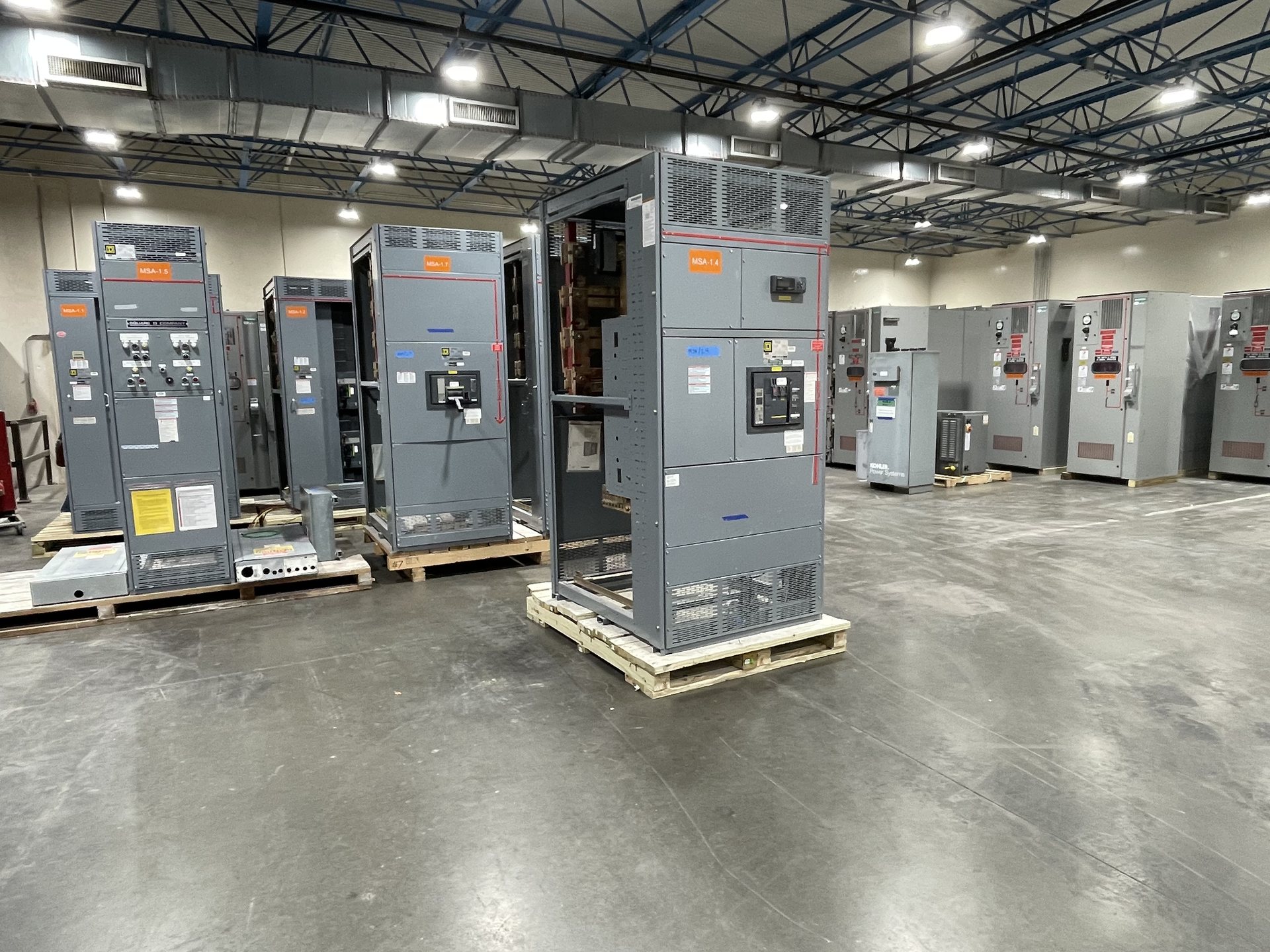
Define the 2000-Amp Main and Breaker Arrangement
Start by identifying what the 2000-amp rating represents in your one-line diagram: the main device, the lineup bus, or both. Specify the system voltage, phase and wire configuration, source arrangement, and whether the service is utility-fed, generator-fed, or supplied by multiple sources. For the main, clarify whether the design calls for a power circuit breaker, its required trip functions, and any drawout or other construction preferences.
A power circuit breaker arrangement must account for more than the frame rating. Provide the intended continuous current, trip settings or adjustable ranges required by the study, interrupting duty, and operating or control-power requirements. If the main must coordinate with upstream protection or transfer between sources, include that functional sequence. These inputs help establish a suitable configuration; final device selection and availability are confirmed during project review.
Choose Bus Configuration for the Actual System
Describe the bus topology needed to support the operating plan: a single main bus, a sectionalized bus with a tie, or another arrangement shown on the approved one-line. A tie breaker changes how sources and loads may be connected, so identify normal-open or normal-closed operation, permitted switching states, and any interlocking requirements. State whether the 2000-amp rating applies throughout the lineup or only to a specified bus section.
Bus material, neutral treatment, grounding, and termination details should be specified alongside ampacity. Tell us whether the design requires a full neutral, a particular neutral-to-phase relationship, an equipment grounding bus, or provisions for future sections. Include conductor entry direction and the intended connection method where known. These details influence section layout and interfaces; they should be reconciled with equipment-room constraints and the project drawings before release.
Plan Feeder Devices Around Connected Loads
Develop a feeder schedule that identifies each outgoing circuit’s load, voltage, phase, continuous or intermittent duty, and required protective-device characteristics. Specify which feeders require power circuit breakers and which may use another device type permitted by the project design. Include spare positions, future feeder provisions, and any critical loads that need a particular source or switching arrangement. A count of feeder ways alone is not enough to establish a workable lineup.
For each feeder, provide the required trip functions, settings or ranges, interrupting duty, and any application-specific constraints from the electrical study. Note cable quantity and termination requirements, conductor entry, and whether the connected load has starting or inrush characteristics that affect protection. Feeder grouping and device placement can affect access, wiring, and future maintenance planning, so review the proposed arrangement against the one-line and equipment-room plan.
Supply Available-Fault-Current and Coordination Inputs
Available fault current at the switchgear is a key equipment-selection input. Provide the utility or source data used for the calculation, including transformer information and impedance when applicable, upstream protective-device details, and conductor lengths and sizes between source and lineup. For multiple sources, generators, or ties, identify the operating configurations that may contribute fault current. The applicable value and assumptions should be tied to the project’s current short-circuit study.
Protection coordination also depends on device settings and operating scenarios, not just nominal ampere ratings. Share the short-circuit and coordination study, time-current curves, selective-coordination requirements where applicable, and any arc-flash study inputs or constraints relevant to the equipment design. Identify the devices that must coordinate upstream and downstream and the intended tie or transfer states. Engineering and equipment suitability must be reviewed against these project-specific inputs.
Coordinate Enclosure, Interfaces, and Retrofit Scope
For a new lineup, provide the available room dimensions, access clearances, equipment orientation, cable approach, and any environmental or enclosure requirements. Identify incoming and outgoing conductor paths, control wiring interfaces, metering needs, and connection points to transformers or downstream distribution. Confirm how the lineup will fit the architectural and electrical plans rather than assuming a standard footprint. The final arrangement depends on the specified devices and required section functions.
For retrofit work, Switchgear Builders Texas supplies new retrofit components only. Provide the existing manufacturer and model information if available, nameplate details, drawings, compartment dimensions, bus and connection data, and clear photographs or field measurements collected by qualified personnel. State which functions must be retained and what interface limits apply. Compatibility, engineering scope, and component availability require review before quotation.
Document the Basis for Quotation and Release
A complete request for pricing should include the one-line diagram, equipment schedule, load and feeder information, fault-current and coordination studies, and relevant specifications. Add required drawings, control schematics, metering details, communication interfaces, and project documentation requirements. Identify applicable codes and standards, submittal expectations, and any required inspection or test documentation. UL 891 applies to switchboard assemblies; for any proposed configuration, verify the applicable standard and listing requirements rather than assuming they apply to all switchgear.
Specify American components as a project requirement and identify any domestic-content documentation the contract calls for. Component origin, engineering, availability, applicable listing, and test documentation must be confirmed for the quoted configuration; no general statement establishes independent verification or compliance with a particular domestic-content rule. We manufacture new equipment to specification, and lead time is subject to project review. Installation, servicing, testing, and energization must be performed by qualified personnel under approved procedures.