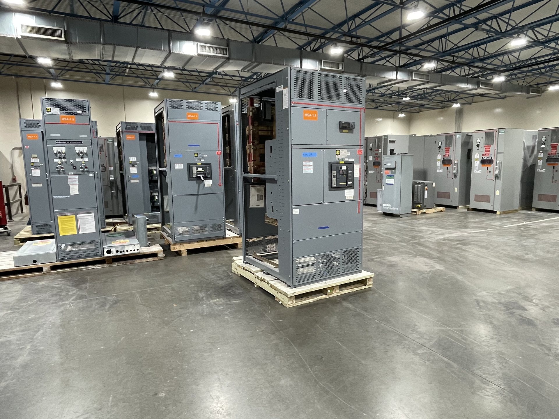
Choose a 3000-Amp Main Breaker Arrangement
A 3000-amp lineup can be arranged around a main power circuit breaker, a main-tie-main scheme, or another project-defined source arrangement. The right choice depends on how many utility or generator sources serve the lineup, whether the bus must be sectionalized, and what operating continuity the facility requires. Specify normal and alternate source conditions, transfer method, preferred tie position, and any limits on paralleling sources.
For each breaker, identify the required continuous-current rating, interrupting capability, trip-unit functions, and any metering or communications needs. These are design inputs, not assumed features of every assembly. Provide the system voltage, grounding method, one-line diagram, and source data so the proposed breaker and lineup can be reviewed against actual conditions. The final configuration and applicable standards should be confirmed for the quoted assembly.
Match Bus Design to the Fault Duty
The 3000-amp designation describes the lineup’s planned current capacity; it does not establish its short-circuit rating. Share the maximum available fault current at the switchgear, source transformer impedance and rating, conductor or busway data, and any utility or generator contribution. Where sources can operate in different combinations, provide the relevant cases rather than a single assumed value. This information supports review of the assembly’s bus and protective-device capabilities.
Bus arrangement is also a physical and operational choice. Define whether the design needs a single bus, split sections, a tie breaker, or provisions for future feeders, and identify the intended sequence of sections and connections. Confirm whether top or bottom cable entry, rear access, or specific termination space is required. These details affect lineup layout and should be resolved early, especially where an existing electrical room constrains the available footprint.
Plan Feeder Breakers Around the Loads
Build the feeder schedule from the loads the switchgear will actually serve. For each outgoing circuit, provide load description, expected demand, conductor information, destination, and requested breaker rating or frame where established by the design. Note motor starting, transformer inrush, large cyclic loads, and any planned load growth. This allows the feeder arrangement to be evaluated as a coordinated lineup instead of treating every circuit as an interchangeable breaker space.
Decide which feeders require dedicated compartments, auxiliary contacts, metering, communications, or other specified provisions. Identify spare breaker positions separately from installed spare breakers, since those are different scope decisions. Provide termination requirements and cable-entry direction for each group of feeders when known. The manufacturer can review the requested arrangement and identify details that need confirmation before a quotation, including space, component availability, and project-specific lead time.
Provide Protection Coordination Inputs
Protection coordination depends on the complete system, not just the 3000-amp main. Submit the coordination study or the available upstream and downstream device data, including protective-device types, trip settings where established, transformer information, and relevant conductor lengths and sizes. State the desired coordination objective and identify any critical loads or selective-tripping requirements. If the study is still in progress, label preliminary assumptions so the equipment scope can be revisited when final results are available.
Also identify ground-fault protection requirements, arc-energy analysis interfaces, zone-selective interlocking, or other protection functions specified by the engineer. These functions depend on system grounding, device selection, wiring, and the approved protection scheme; they should not be inferred from the ampacity alone. Qualified personnel must perform installation, servicing, testing, and energization under approved procedures. Settings and final coordination remain subject to engineering review of the actual system.
Define Existing-System and Retrofit Boundaries
For a replacement or expansion project, send existing one-line diagrams, equipment nameplate information, available dimensions, cable locations, and photographs or drawings that clearly show the relevant interfaces. Identify what remains in service, what will be removed, and where the new lineup must connect. Confirm room clearances, access routes, lifting constraints, conduit locations, and any restrictions on outage duration. These details help distinguish electrical compatibility from physical fit before equipment is quoted.
We supply new switchgear and new retrofit components only. For retrofit scope, identify the exact equipment and component configuration required and provide manufacturer and model information when available. Compatibility must be evaluated against the existing assembly and its documented ratings; a component that appears to fit may not be electrically or mechanically suitable. Provide the desired scope boundary so the quotation can state what is included and what remains by others.
Assemble a Quote-Ready Specification Package
A useful request for pricing includes the one-line diagram, load and feeder schedule, system voltage, grounding details, available-fault-current data, coordination information, and required breaker and bus arrangement. Add the project location, target schedule, shipping destination, applicable project specifications, and requested drawing or test documentation. If a design item is unresolved, identify the decision owner and the date it is expected to be finalized rather than presenting an estimate as a confirmed requirement.
State any requirement for American components directly in the specification. We build to customer specifications using American components, but component origin and documentation must be confirmed for the quoted configuration; domestic-content compliance is not assumed. UL 891 is a switchboard standard, not a blanket listing for all switchgear, so verify the applicable standards and listing for the specific configuration. Availability, engineering, lead time, and documentation are reviewed for each quotation.