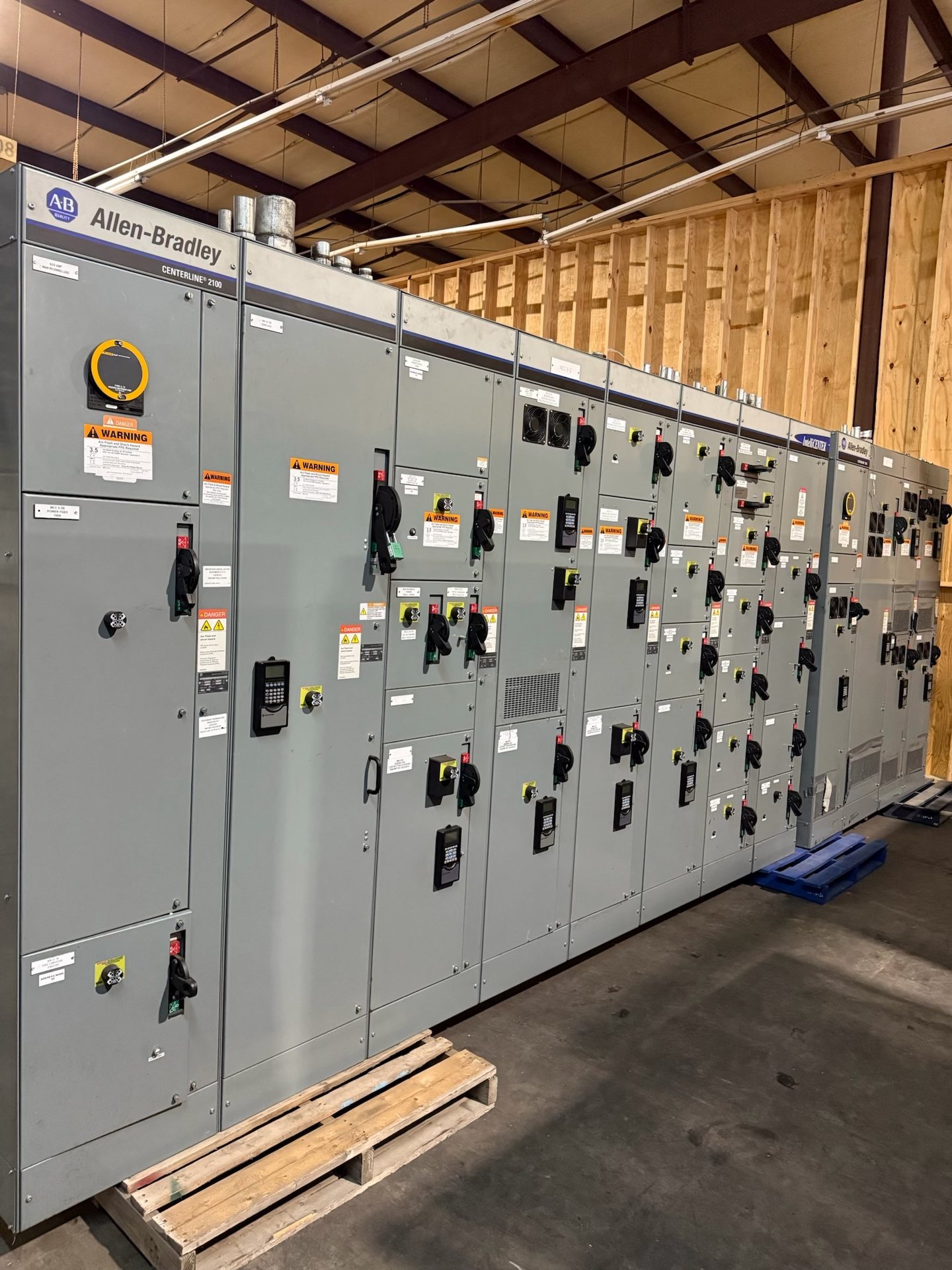
Set the voltage class and system basis
Start with the system’s nominal voltage and the maximum voltage the equipment must accommodate. Confirm whether the application is utility service, a main distribution lineup, a generator connection, or a feeder installation, since the source, grounding method, and operating arrangement affect equipment requirements. For an Amarillo project, provide the one-line diagram and identify the system frequency, grounding method, and points of connection. These inputs establish a meaningful basis for selecting the switchgear configuration.
Do not treat a voltage class in a project title as confirmation that a particular lineup is available or suitable. The quotation review needs the required ratings and the actual system conditions, including normal and emergency operating modes where relevant. Identify future feeder additions or planned source changes as well. We confirm engineering and availability for the specified configuration rather than assuming that a standard arrangement will fit every utility or facility system.
Choose the breaker and bus arrangement
Describe what each breaker must control and how the lineup should operate. The scope may involve an incoming device, feeder breakers, bus sectionalizing, or a tie arrangement, but the correct choice depends on the one-line diagram and operating sequence. State which sources can operate together, whether transfer is manual or automatic, and which loads must remain energized during maintenance or a source interruption. These details help define interlocks and control interfaces without assuming a particular topology.
For each breaker position, provide the required interrupting and continuous-current ratings, protection functions, and any specified drawout or fixed construction preference. Explain access and maintenance constraints, including lineup orientation and room clearances, for the design review. If the project calls for new retrofit components for existing equipment, identify the original manufacturer, model, relevant nameplate data, and interface drawings. Compatibility must be reviewed; a replacement component should not be presumed to fit from voltage alone.
Define relay and control interfaces
List the protective functions and coordination requirements for each controlled circuit. Relay selection and settings depend on the protection study, instrument transformer ratios, source characteristics, and coordination with upstream and downstream devices. Provide the study or its design criteria, identify required trip and alarm contacts, and describe any communications or remote-control needs. This gives the equipment scope a clear boundary and helps the project team coordinate switchgear controls with plant or utility systems.
Document the interfaces expected between the switchgear and external systems, such as supervisory control, metering, annunciation, or a transfer scheme. Identify preferred communication protocols only where the project has established them, and specify who supplies network equipment, control wiring beyond the lineup, and final relay settings. We can review these requirements during quotation, but suitability and documentation must be confirmed for the exact configuration. Qualified personnel must perform installation, testing, and energization under approved procedures.
Coordinate cable entry and terminations
Cable arrangements affect compartment design, access, and installation planning. For each incoming and outgoing circuit, provide conductor material, insulation type, size and quantity, cable direction, and the intended termination method. Confirm whether cables enter from above or below and note conduit, trench, or duct-bank constraints. Include the cable data and termination requirements from the project documents so the proposed interfaces can be reviewed before equipment details are finalized.
Check that the planned cable approach leaves adequate space for the specified terminations, bending requirements, and installation sequence. Identify whether shield grounding, stress-control components, or a particular lug or connector interface is specified by the cable or project design. Avoid relying on a general statement such as “standard cable entry”; actual dimensions and interfaces should be confirmed against the selected equipment and field layout. Coordinate these details with the electrical contractor and design team before release.
Match insulation and fault-duty requirements
Specify the insulation system and environmental conditions required for the installation rather than assuming a default construction. Provide the applicable system voltage, altitude and ambient conditions, indoor or outdoor setting, and any exposure to dust, moisture, or other site conditions that could affect the design. For an Amarillo destination, these are project inputs to verify, not grounds to assume a particular local installation environment. The engineering review should use the actual site information supplied by the project team.
Fault duty must be based on the available short-circuit current at the switchgear location and the required clearing time, with coordination among the source, protective devices, and equipment ratings. Supply the latest fault study or clearly identify any study still pending. Ask the engineer of record to resolve assumptions about future utility contribution, motor contribution, or alternate sources. We confirm the applicable ratings and supporting documentation for the quoted configuration; no generic rating should be taken as a project guarantee.
Prepare a complete quotation and submittal package
A useful request for pricing includes the one-line diagram, equipment schedule, load and feeder list, protection criteria, cable information, and project specifications. Add the required lineup dimensions, access constraints, control interfaces, and delivery destination in Amarillo. Identify which documents are preliminary and which are approved for design. A clear package reduces ambiguity in scope and gives the manufacturer a basis to review the configuration, confirm availability and lead time, and identify items that need engineering clarification.
State whether the request is for a complete new lineup or new retrofit components, and clearly describe any existing-equipment interfaces. Specify requested component origin and any project documentation requirements, while recognizing that origin, applicable standards, listing status, and test documentation are confirmed for each quotation and configuration. UL 891 applies to switchboards, not automatically to medium-voltage switchgear; verify the applicable standards and any required listing for the proposed assembly. Review approved submittals before release, and have qualified personnel complete field work under approved procedures.