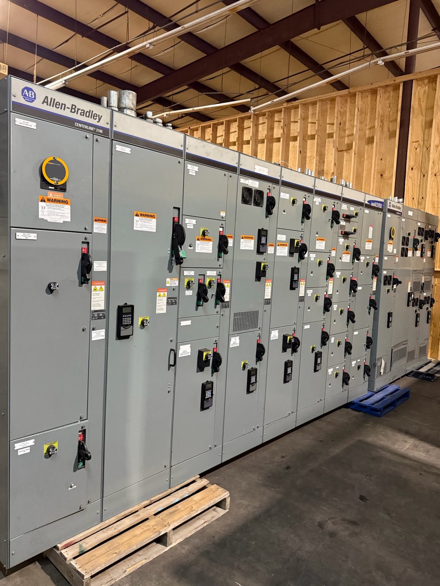
Define the Arlington project's voltage class and system conditions
Start by documenting the system's nominal and maximum operating voltage, frequency, grounding method, and intended point of connection. Confirm whether the equipment is for a utility interface, facility distribution, generation connection, or another application. These details establish the voltage class and influence insulation coordination, metering, protection, and the arrangement of the incoming and outgoing circuits. A project location in Arlington does not, by itself, determine any of these electrical design parameters.
For a quotation, provide available one-line diagrams, utility or facility interface requirements, transformer data, and the expected operating configuration. Identify normal and alternate sources, tie operation, future feeder provisions, and any restrictions on equipment footprint or access. If existing gear is involved, supply its nameplate information and connection details where available. We use the submitted information to assess the requested scope rather than assume that a nominal voltage alone defines a compatible assembly.
Choose a breaker and bus arrangement for the operating sequence
The breaker arrangement should reflect how the Arlington facility will isolate, transfer, and restore circuits. Establish the number and purpose of incoming sources, feeder circuits, bus sections, and ties, then describe which devices may operate together and which states must be prevented. A single-ended lineup, sectionalized bus, or other scheme has different implications for continuity, interlocking, protection, and maintenance planning; the preferred arrangement follows the operating study and owner requirements.
Specify breaker type and operating features only after confirming the system and project requirements. Clarify whether the design calls for withdrawable or fixed devices, local and remote control, electrical or mechanical interlocks, and auxiliary contacts for status indication. Identify intended spare ways and future circuit additions instead of relying on unspecified expansion space. We can review new equipment or new retrofit components, but fit and interface compatibility with existing equipment must be established from drawings and verified project information.
Coordinate protective relays and control interfaces
Relay scope should follow a documented protection philosophy, not a generic device list. Identify the circuits requiring protection, the functions required by the study, instrument-transformer ratios and accuracy needs, trip and close logic, and any communications or event-reporting requirements. Confirm how relays will receive current and voltage inputs and how they interact with breaker trip circuits, lockout functions, and upstream or downstream protection. Settings and coordination remain project-specific engineering decisions.
Provide control schematics, preferred interface conventions, communication protocols, and requirements for alarm, status, metering, and remote commands. Clarify which signals are supplied by the switchgear and which must connect to a plant control system, utility interface, or customer-furnished equipment. Identify control-power source and acceptable circuit supervision requirements. For quotation review, relay model availability, component origin, and included documentation must be confirmed for the proposed configuration rather than assumed from a general product description.
Match cable terminations to conductors and site routing
Cable entry and termination details can determine compartment dimensions and practical installation sequencing. Document conductor material, cable count and size, insulation type, shielding, and whether the connection is incoming, outgoing, or a bus tie. Provide cable approach direction, trench or conduit constraints, bending-space requirements, and the intended termination method. These inputs help establish the interface between the switchgear and site-installed cables without assuming that every cable accessory or termination is included in the equipment scope.
Ask the project team to confirm termination clearances, stress-control requirements, grounding and shield connections, phase identification, and any barriers or access restrictions. Where existing equipment is retained, drawings and field-verified interface dimensions are important before specifying new retrofit components. State who furnishes and installs cables, lugs, connectors, and termination kits, and what interface drawings are required. Installation and commissioning must be performed by qualified personnel using approved project procedures.
Evaluate insulation and available fault duty
The insulation system and withstand requirements must suit the specified voltage class, operating environment, and system grounding conditions. Describe indoor or outdoor use, ambient and altitude conditions, contamination or moisture concerns, and any space or ventilation constraints. Confirm the required insulation level and applicable design criteria with the responsible engineer and project specifications. Do not infer suitability from voltage alone: environmental exposure and system characteristics can affect the equipment configuration and the documentation needed for review.
Fault-duty selection requires the available short-circuit current at the proposed connection point, the relevant clearing time, and the system's operating scenarios. Include utility data, transformer impedance, generator or motor contributions when applicable, and anticipated changes to the source configuration. The selected assembly and breakers must be evaluated against those project conditions. Provide the short-circuit and coordination studies if available, and identify any required withstand or interrupting criteria so the quotation can be reviewed against a defined basis.
Prepare a complete specification and quotation package
A useful request for pricing combines a one-line diagram, equipment schedule, applicable project specifications, site conditions, and a clear scope boundary. Include required lineup arrangement, ratings, relay and control interfaces, cable termination details, fault-duty basis, and any new retrofit component requirements. Identify requested drawings, bills of material, manuals, test records, and other submittals. State the project schedule and delivery destination in Arlington, while recognizing that engineering review and lead time are confirmed for each quotation.
Switchgear Builders Texas manufactures and supplies new equipment and builds to specification using American components when requested. Component origin, availability, engineering scope, test documentation, and applicable standards must be confirmed for the quoted configuration; domestic-content compliance is not implied. UL 891 applies to switchboard assemblies, not as a blanket standard for medium-voltage switchgear. For any proposed configuration, verify the applicable standards and listing requirements. Installation, servicing, testing, and energization require qualified personnel working under approved procedures.