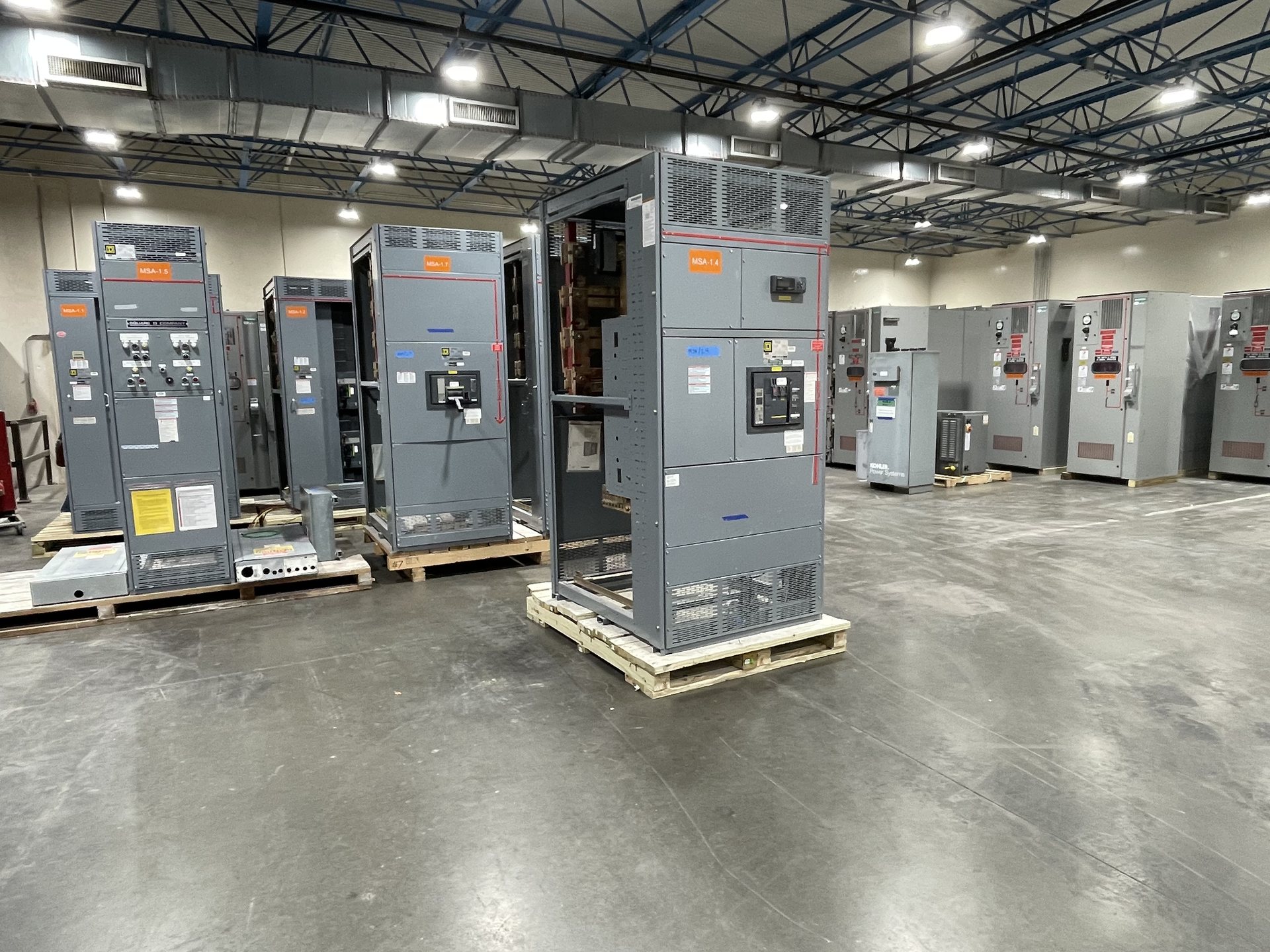
Translate electrical duty into a fabrication basis
Start with the equipment’s documented current requirements and operating conditions, rather than selecting a busbar from a nominal current value alone. The design review needs to establish the applicable continuous current, system voltage, phase configuration, frequency where relevant, and expected fault duty. Available information may include approved one-line diagrams, switchboard or switchgear drawings, equipment schedules and the existing assembly’s nameplate data. Missing or conflicting values should be resolved before dimensions are finalized.
Current capacity depends on the complete arrangement, including conductor material and dimensions, spacing, enclosure conditions, joints and heat dissipation. A drawing that shows only bar width and thickness may not establish suitability for the intended assembly. Identify whether the part is a main, vertical, horizontal, neutral, grounding or connection bus, and explain its function in the circuit. We review the submitted basis for the quoted configuration; project engineering and applicable ratings must be confirmed for each order.
Define phase arrangement and physical routing
Phase arrangement determines more than the order of conductors. Provide the phase sequence, orientation, spacing, transitions between planes, and any required neutral or grounding conductor arrangement. Drawings should make clear the view direction and identify incoming and outgoing connections so that a mirrored or rotated part is not mistaken for the intended layout. Where the assembly has multiple sections, show how busbars continue across section joints and which interfaces are within scope.
Routing must account for the switchgear’s available space and nearby components. Call out barriers, insulation supports, doors, cable spaces, instruments, breakers and other obstructions that affect the bar path or access to connections. For a new assembly, coordinate these details with the overall equipment design. For a new retrofit component, provide reliable as-built dimensions and interface drawings; the original manufacturer’s drawing alone may not reflect later field modifications. Fit and clearances require confirmation against the actual configuration.
Engineer support points and mechanical fit
Busbar supports restrain conductors and maintain intended spacing under operating and fault conditions. Supply support locations, attachment details, required clearances and the design information used to establish mechanical duty. The number and position of supports affect free spans and the loads transferred to insulators, brackets and enclosure structure. If the project has specified fault-current withstand requirements or a particular support system, include that information in the RFQ rather than treating supports as interchangeable hardware.
Fabrication dimensions should reference stable datums, such as mounting faces, section boundaries or established connection centers. Identify tolerances for overall length, offsets, flatness, hole location and alignment where they affect installation or joint contact. Also note enclosure restrictions, access limitations and required separation from adjacent phases or grounded metal. These details help resolve whether a formed part will clear its surroundings and meet its interfaces; they do not substitute for qualified review of the complete assembly design.
Specify terminations, holes and joint interfaces
For each termination, show the mating component and the intended connection plane. Provide hole count, pattern, diameter, edge distance, orientation and any slot dimensions, along with the required contact area and access for assembly. Identify whether the busbar connects to a breaker, cable terminal, transformer connection, splice plate or another bus section. Do not assume that two parts with matching hole spacing are compatible if their thickness, alignment, contact surface or fastening arrangement differs.
Joint requirements deserve particular attention in retrofit work. Record the location and dimensions of mating bars, splice plates, fasteners and any barriers or insulating parts that affect the connection. State whether existing hardware is retained or new connection components are required, and identify which items are included in the requested scope. The quotation review can then address the specified new parts and interfaces. Final joint design, hardware suitability and assembly procedures remain subject to the equipment design and applicable project requirements.
Choose material, forming and finish requirements
Specify the required conductor material and any project restrictions on component origin. Material choice affects conductivity, weight, joint design, forming and the dimensions needed for the intended duty. We build to the customer’s specification using American components as requested, but component origin, availability and documentation must be confirmed for each quotation. A request for domestic-content or other procurement compliance should identify the exact contractual requirement; component sourcing by itself does not establish compliance with a particular rule.
Describe the required fabrication operations: cut lengths, bends, offsets, edge treatment, drilled or slotted features, and surface finish. Note any specified plating, coating, insulation or other treatment, including the portions that must remain suitable for electrical contact. Forming sequence and bend geometry need to preserve the intended fit and avoid interference with supports or neighboring parts. State whether the work concerns a new equipment assembly or new retrofit components.
Review drawings, inspection and purchasing scope
A practical RFQ package includes the project one-line, assembly and busbar drawings, relevant schedules, electrical duty, interface dimensions, material and finish requirements, quantity, and requested delivery destination. Mark drawings with revision status and identify which documents govern if they conflict. For retrofit parts, add measured field dimensions, photographs where useful, and a clear description of the existing equipment. These records let the manufacturer review manufacturability and identify unanswered questions before pricing is finalized.
Agree on inspection and document expectations before release, such as dimensional checks, material records or other project-specific records. Do not assume that a particular test, certification, listing or document is included unless it is confirmed for the configuration and quotation. UL 891 applies to switchboards; it is not a blanket listing for all switchgear or an automatic claim for a fabricated busbar part. Verify applicable standards and assembly listing requirements. Installation, servicing, testing and energization require qualified personnel working under approved procedures.