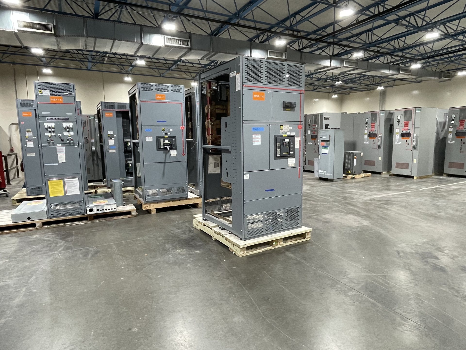
Electrical and Mechanical Design Scope
Design coordination begins with the intended system function and the information that governs the assembly. Share one-line diagrams, load and fault information, voltage and current requirements, incoming and outgoing arrangements, protection objectives, and applicable project specifications. Identify the installation environment, available space, cable entry and termination needs, and any interface constraints. These inputs help establish what engineering work belongs in the proposed scope rather than assuming a standard design fits.
Electrical and mechanical design details should be reviewed together. For example, device selection and bus arrangement affect enclosure layout, access, clearances, and connection points. Confirm who provides sealed engineering, calculations, coordination studies, and approval drawings, if required; these are not automatically included in equipment fabrication. The quotation should identify the design basis, customer-furnished information, review milestones, and unresolved decisions before a configuration or schedule is represented as firm.
Customization to Project Requirements
Customization can address project-specific arrangement, control and metering needs, labeling, cable access, enclosure details, and selected components. Start by separating mandatory requirements from preferences, then identify the specification paragraph, drawing, or operational need behind each request. Confirm environmental conditions, access direction, maintenance clearances, and restrictions on room layout. This makes it easier to assess feasibility and to document the proposed configuration without implying that every requested feature is available in every assembly.
Customers may specify American components, but component origin and availability must be confirmed during quotation and engineering review. A component preference does not by itself establish compliance with domestic-content requirements or a particular procurement rule. Provide acceptable alternatives, required manufacturer documentation, and any restrictions on substitutions. The quotation should state which choices are included, which remain pending, and whether a requested change could affect design review, fabrication planning, documentation, or lead time.
Integration and Interface Coordination
An assembly’s interfaces can determine whether it fits the broader electrical project. Identify upstream and downstream equipment, protective-device coordination responsibilities, control power sources, metering signals, communications protocols, and required connection points. Share interface drawings and schedules where available, and clarify which party owns each connection or configuration decision. Integration scope should be defined around the actual project boundary; it should not be assumed to include field wiring, system programming, or coordination with equipment not included in the quotation.
For replacement or expansion work, document existing equipment interfaces without relying on visual similarity alone. Useful records include nameplates, dimensions, bus and cable arrangements, control schematics, available space, and the operating constraints of the facility. Confirm whether the project needs drawings for review, terminal schedules, communications information, or coordination with other vendors. These details help identify dependencies early, while final compatibility and interface requirements remain subject to engineering review and approved project documents.
Fabrication of New Equipment
Fabrication scope starts with an approved equipment configuration, defined materials and components, and a clear set of project documents. Switchgear Builders Texas supplies new equipment manufactured to the agreed specification. Before release, establish drawing approval responsibilities, revision control, component selections, labeling requirements, and the records expected with the assembly. Confirming these items reduces ambiguity between the design intent and the equipment described in the quotation.
Project planning should also account for shipping destination, handling constraints, access at the receiving site, and the sequence in which equipment is needed. Provide packaging or delivery requirements that affect the shipment, along with any site restrictions relevant to dimensions or unloading. Lead time is subject to project review, component availability, configuration, and approval timing; it is not a fixed promise before those factors are assessed. The quotation should distinguish confirmed scope from assumptions and open items.
Verification and Documentation
Verification requirements should be specified rather than inferred from a product category. Tell us which drawings, inspection records, test documentation, or other submittals the project requires, and identify the governing specification or acceptance criteria. Confirm whether witness points, customer review, or particular records are requested and whether they affect the project schedule. The available verification scope and documentation must be confirmed for the quoted configuration; no specific test result or package should be assumed in advance.
Standards and listing requirements also need configuration-level review. UL 891 applies to switchboard assemblies, not as a blanket listing for all switchgear, and the applicable standards and listing status should be verified for the proposed assembly. State the required standard, jurisdictional or project conditions, and documentation needed for acceptance. Installation, servicing, testing, and energization must be performed by qualified personnel under approved procedures; equipment documentation does not replace site-specific safety controls.
Modernization with New Retrofit Components
Modernization scope is limited to new equipment and new retrofit components. It can be considered when an existing installation needs a replacement assembly, updated interface, or a defined new component configuration, subject to engineering review. Begin with the existing equipment identification, drawings, dimensions, ratings, connection details, and the reason for the change. Clarify what remains in service, what is replaced, and whether the work is a new assembly or a new retrofit component; do not assume interchangeability from appearance or legacy descriptions.
A practical review compares the existing conditions with the requested operating requirements and project constraints. Provide photographs and records only as supplements to legible nameplate data and drawings, and identify outages, access limits, and required coordination with the site team. Confirm responsibility for field verification, installation planning, and acceptance documentation. Compatibility, engineering, component origin, applicable standards, and lead time are determined for each quotation.