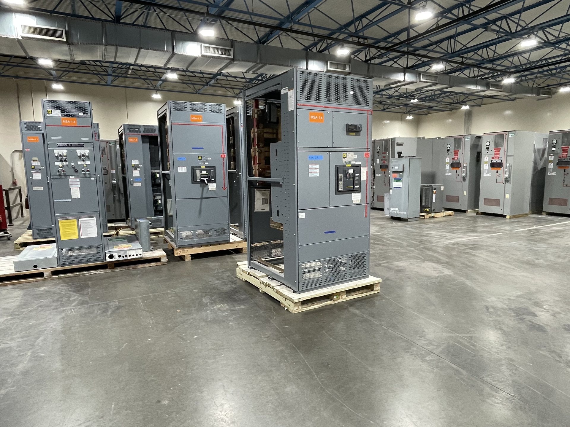
Electrical Design Capabilities
Our design process organizes the information needed to define a switchgear assembly before a configuration is quoted. We review the intended application, system arrangement, load characteristics, available source information, protection approach, control functions, and project constraints. The resulting design basis can be used to develop a one-line diagram and equipment schedule that make the proposed scope visible to the project team.
To begin, provide the latest one-line if available, service and distribution requirements, load list, site or room constraints, and governing project specifications. Identify what is fixed and what remains open for engineering review. For retrofit components, include the existing equipment manufacturer and identification details, drawings, photographs, and interface dimensions where available. We supply new equipment and new retrofit components; the proposed scope must be confirmed against the information provided.
Turn Load Data into a Defined Equipment Schedule
A useful equipment schedule connects each served load or feeder to its intended circuit position and required device characteristics. The design review should clarify load type, operating duty, criticality, expected growth, and whether loads require dedicated feeders or coordinated groupings. These distinctions affect how the assembly is arranged and what information needs to appear on the one-line and schedule.
Load data should distinguish connected load from the demand basis used by the project engineer, and should identify motor, transformer, electronic, or other characteristics that may affect equipment selection. Confirm feeder quantities, spare or future positions, naming conventions, and any required metering points. We use the project’s stated design criteria rather than assuming missing values; unresolved assumptions and schedule gaps should be called out for review before quotation.
Document Sources and System Arrangement
Source information establishes how the proposed equipment fits into the electrical system. The design basis should identify utility or generator sources, transformer relationships, normal and alternate feeds, tie arrangements, and any planned transfer or paralleling functions. A one-line should show the intended relationships clearly enough for reviewers to trace the path from source through protective devices to the loads served.
Please identify the project’s nominal system voltage, phase and wire arrangement, grounding method, source contribution data when available, and whether the equipment is service, distribution, or a downstream assembly. Note any operating modes that change the source path, including transfer conditions or normally open ties. These details are design inputs, not guaranteed equipment ratings or availability; configuration and applicable limits must be confirmed for the specific project.
Coordinate Protection and Interrupting Requirements
Protection requirements should be coordinated with the system study and the project’s operating objectives. Relevant design inputs may include available fault current, protective-device functions, trip or fuse criteria, selective coordination requirements, arc-energy study assumptions, and downstream device information. The one-line and equipment schedule should identify the intended protective devices and settings basis without substituting for the engineer’s system calculations.
For review, distinguish values that are established by a study from values still awaiting utility data, equipment submittals, or field verification. Identify any required trip-unit features, ground-fault functions, zone-selective interlocking, or communications interface, as applicable to the specified design. Protection selections and documentation depend on the confirmed configuration. We do not infer a study result from a general description or treat a requested feature as verified performance.
Define Control, Metering, and Interface Requirements
Control design translates operating sequences into equipment interfaces and documented functions. Describe which devices are controlled locally or remotely, what initiates transfer or interlocking, what status and alarm points are required, and how control power is intended to be provided. A clear sequence of operation helps identify control components, terminal interfaces, and information that belongs on drawings and schedules.
For metering and communications, specify the measured quantities, display or monitoring expectations, protocol or network interface where required, and who supplies external devices or wiring. Identify permissives, emergency signals, and interfaces to generators, building controls, or other systems. Open questions should be recorded as review items rather than silently converted into design assumptions. Final control scope depends on project requirements and the confirmed equipment configuration.
Prepare Review-Ready Drawings and Project Records
Design-review deliverables should let the project team check both intent and scope. Depending on the agreed quotation, the document package may include a project-specific one-line, equipment schedule, configuration notes, and identified design assumptions or exclusions. Reviewers can then compare feeder counts, device functions, source relationships, control interfaces, and naming against the contract documents before the equipment configuration is finalized.
A productive review cycle starts with revision-controlled inputs and a named point of contact for consolidated comments. Return markups that distinguish required corrections from preferences, and identify which documents govern if drawings or specifications conflict. Confirm the expected submittal format, review milestones, and record-document needs before release. The exact deliverables and timing are project-specific and should be stated in the quotation; no document set is implied until its scope is agreed.
Scope New Equipment and Retrofit Components
For new equipment, design review can establish the assembly arrangement, feeder schedule, protective-device intent, control requirements, and project interfaces. For a retrofit, start by defining which new components are requested and how they must interface with the existing installation. Existing conditions, available space, connection details, control wiring, and equipment identification all affect whether the proposed new components can be scoped responsibly.
Provide existing drawings and verified field information, and flag any dimensions or electrical data that remain unconfirmed. We supply new equipment and new retrofit components only. Before requesting pricing, align the design basis, document scope, component-origin requirements, and applicable standards. UL 891 applies to switchboards; listing and standards must be verified for the specific configuration.