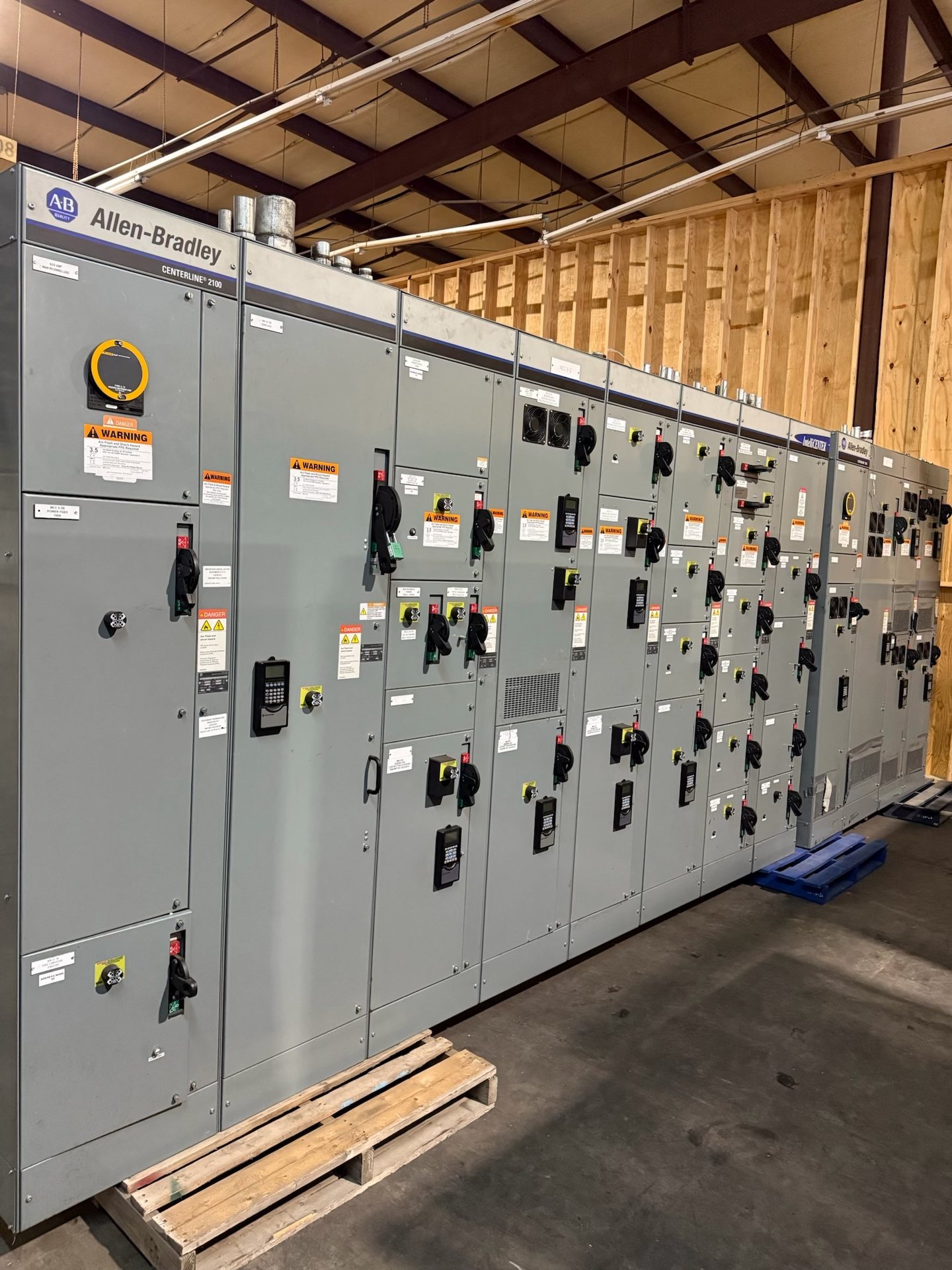
Coordinate Utility Metering Before Selecting the Assembly
Metering is often the first interface to resolve because the serving utility determines where and how service energy is measured. Confirm whether metering is utility-furnished or incorporated into the specified equipment, the required meter socket or instrument-transformer arrangement, and any enclosure, access, sealing, or compartment requirements. Provide the utility’s current service manual or written project requirements; assumptions based on another building or service territory may not apply.
The electrical one-line should show the service point, metering location, service disconnects, and downstream distribution. Clarify whether the utility requires a particular compartment sequence, provisions for current transformers, or separation between metering and customer equipment. Identify who supplies metering devices and who is responsible for final utility acceptance. These details allow the assembly configuration to be reviewed against the actual interface instead of relying on a generic commercial service layout.
Define the Service Disconnect Arrangement
Describe the intended service disconnect configuration: the number and type of disconnecting devices, their ratings and functions, and how they relate to the service conductors and downstream feeders. Provide the one-line diagram, load and feeder schedules, and any specified arrangement for grouping or identifying service disconnects. The applicable electrical design and authority requirements must be established for the project; a product quotation is not a substitute for that review.
Also identify equipment boundaries that affect the assembly, including transitions to distribution sections, provisions for future circuits, and any required barriers or compartment divisions. Where a retrofit is involved, state whether the scope is a new complete assembly or new replacement components intended for existing equipment. Include the existing equipment manufacturer and relevant catalog or drawing information when available. Compatibility depends on verified dimensions, interfaces, and ratings, not on a general description such as “replacement disconnect.”
Establish Available Fault Current and Required Ratings
Fault duty must be based on the available fault current at the equipment location and the electrical system conditions used by the design team. Supply the utility’s available fault-current information, transformer data where applicable, system voltage, grounding arrangement, and the engineer’s specified equipment ratings. If the source configuration or utility data is still pending, identify that status so the quotation can state which design inputs remain subject to confirmation.
The equipment’s interrupting and short-circuit ratings must be evaluated for the specified configuration and coordination with upstream and downstream devices. Do not assume that a rating appropriate for one service location is suitable at another, or that a component rating alone establishes the rating of the completed assembly. Provide any required coordination study criteria or protection-device selections. Applicable ratings, engineering, and supporting documentation should be confirmed for the quoted configuration.
Reserve Practical Space for Incoming Conductors
Incoming conductor space is a physical design requirement, not a detail to leave until installation. Provide the conductor material, quantity, size, insulation or cable type, and expected entry direction, along with conduit count and trade sizes when known. State whether the design uses a top or bottom entry and identify routing constraints, pull space needs, and any planned transition from utility conductors to customer conductors. These inputs help determine whether the proposed termination area is workable.
Building conditions can constrain the equipment footprint and conductor approach. Share the available wall or floor space, room access path, working-space constraints provided by the project team, and nearby structural or mechanical obstructions. For replacement work, supply accurate field dimensions and photographs or drawings of the existing location, including conduit entry positions. Do not rely on nominal enclosure dimensions alone; final clearances and installation conditions require review by the project’s qualified design and installation personnel.
Provide the Documents Needed for a Compatible Selection
A focused request for pricing should include the latest one-line diagram, panel or feeder schedules, service voltage and phase, design load information, available fault-current data, utility metering criteria, and the project specification. Add the requested number of sections or devices, enclosure and environmental requirements, conductor entry details, and any requirements for future capacity. Mark documents with revision dates and identify unresolved items so the quotation can distinguish confirmed scope from assumptions.
For new retrofit components, include existing assembly nameplates, equipment drawings, breaker or disconnect details, bus and connection information, and verified field measurements where available. Identify the exact component being replaced and the intended interface with retained equipment. Photographs can help explain conditions but do not establish dimensions or electrical ratings. We review the supplied information to define a manufacturable scope; compatibility and availability remain subject to project-specific engineering review.
Review Standards, Documentation, and Project Timing
State the applicable project specifications and requested standards or listing criteria for the exact assembly. UL 891 applies to switchboards; it should not be treated as a blanket listing for every configuration or for other classes of switchgear. Listing status and applicable standards must be verified for the proposed equipment. If the project requires drawings, bills of material, rating information, or other submittals, identify them at quotation so the required documentation can be evaluated for the configuration.
Lead time depends on the approved scope, component availability, engineering inputs, and review milestones. Provide the required-on-site date, drawing review schedule, procurement constraints, and any phasing needs, then request confirmation with pricing. Component origin and test documentation are also configuration-specific and should be addressed in the quotation; specifying American components does not itself establish independent origin verification or compliance with domestic-content rules. Installation, servicing, testing, and energization require qualified personnel following approved procedures.