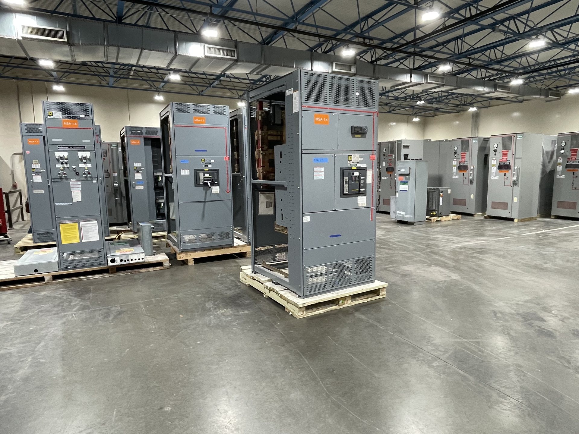
From project one-line to lineup concept
The one-line diagram establishes the electrical relationships the lineup must support: incoming sources, bus sections, feeders, ties, metering, and protective devices. We use it as a design input, not as a complete manufacturing instruction. For a useful review, provide the latest revision and identify the intended operating arrangement, normal and alternate sources, required transfer or isolation functions, and any equipment interfaces outside the lineup.
We compare those requirements with the proposed sections and call out information that could change the design, such as an undefined tie sequence, inconsistent circuit identifiers, or a feeder shown without a confirmed load or protective-device requirement. Before construction, the responsible project parties must resolve these items and approve coordinated drawings. A one-line can guide the design process, but it does not replace approved construction documents or confirm that every detail is final.
Utility requirements and service coordination
Utility criteria can affect the incoming section, metering provisions, service disconnect arrangement, grounding approach, and coordination with the utility’s facilities. Share the utility’s current service requirements and identify which details are mandatory, pending review, or still under discussion. Clarify who is responsible for submitting drawings to the utility and obtaining its acceptance; a project specification or preliminary one-line alone does not establish utility approval.
Where utility input remains open, record the assumptions used for the proposed design and identify the decisions that must be confirmed before release. Ask whether the utility requires particular metering compartments, access clearances, instrument-transformer provisions, barriers, or drawing formats. These are project-specific coordination questions, not universal features. Final construction should reflect the applicable requirements confirmed for the service and the approved equipment configuration.
Ratings, protection, and equipment boundaries
Ratings must be selected as a coordinated set, based on the electrical system and project documents. Relevant inputs may include system voltage, continuous current, available fault current, protective-device interrupting and withstand requirements, bus arrangement, and environmental conditions. Provide the source of each value and identify values awaiting the engineer’s or utility’s confirmation. A title or early equipment schedule is not enough to establish the final rating or guarantee that a particular configuration is available.
Define the boundary between the lineup and connected equipment, including conductors, transformers, generators, control systems, and any existing gear. Confirm which protective functions and controls belong in the scope, who supplies external devices, and what interface signals or terminals are required. The responsible design team must verify coordination and application suitability. Applicable standards and any requested listing must be checked against the actual configuration; UL 891 applies to switchboards, not automatically to every type of switchgear assembly.
Site constraints and physical configuration
A workable electrical design also has to fit the installation space and the route to it. Supply the available room dimensions, access and working-clearance requirements, door and aisle locations, cable entry direction, and constraints for moving equipment from delivery point to final position. Identify overhead obstructions, floor or housekeeping-pad conditions, adjacent equipment, and any environmental exposure that affects the installation. These details help the project team assess section arrangement and connection access before drawings are finalized.
Confirm the preferred lineup orientation and the locations of incoming and outgoing connections, while distinguishing preferences from fixed site conditions. If the room is changing or field measurements are provisional, label them accordingly and assign responsibility for verification. We use documented constraints to develop a proposed arrangement; the installer and project team remain responsible for confirming that the approved design fits the actual site and meets applicable clearance and installation requirements.
Document control and release for construction
Manufacturing begins with a controlled definition of what is being purchased. Typical review documents may include the project specification, one-line, equipment schedule, utility criteria, interface requirements, and site information. Identify document revisions, conflicts, and approval responsibilities. A quotation or preliminary drawing is not a substitute for the final approved configuration, and a design input should not be treated as authorization to build unless the project’s release process makes that approval explicit.
Review drawings for section order, circuit names, device functions, connection locations, metering and control provisions, and interfaces with field wiring. Resolve comments in a documented revision cycle and confirm which revision governs construction. Requests made after approval can affect design review, component selection, schedule, and cost; their effect must be assessed rather than assumed. Final scope and documentation are established through the project-specific quotation, approved drawings, and agreed release requirements.
New equipment, retrofit components, and purchasing
We manufacture and supply new equipment and new retrofit components only. For a retrofit scope, provide the existing equipment manufacturer and model information, clear photographs or drawings where available, compartment and connection details, device functions, and the purpose of the change. The project team should confirm the condition and dimensions of existing gear and identify which components are to be replaced, retained, or interfaced. Compatibility must be evaluated for the specific application; a description such as “replacement breaker” alone is not a complete specification.
For pricing, share the required configuration, project location, requested delivery needs, drawing and documentation expectations, applicable utility criteria, and any specified American-component requirements. Component origin and availability are confirmed during quotation; customer requirements do not by themselves establish independent domestic-content verification or regulatory compliance. We serve Texas from the United States and ship nationwide. Lead time, engineering scope, standards, and test documentation are subject to project review and confirmation for the quoted equipment. Installation, servicing, testing, and energization must be performed by qualified personnel under approved procedures.