Can an Existing Switchgear Lineup Be Expanded?
Sometimes. An expansion is a candidate for further engineering when the existing lineup’s design records, ratings, condition, and interface details support the proposed addition. A spare compartment or unused breaker position is not, by itself, proof that the bus can carry more load or that the assembly can withstand the available fault current. The decision should be based on the complete lineup and the new operating duty.
Start by defining the added load, its operating profile, the required switching or feeder function, and the intended point of connection. Then gather the switchgear drawings, nameplate information, breaker data, maintenance history, and any prior modification records. If essential details are missing or contradictory, treat compatibility as unconfirmed until the equipment is identified and the design is reviewed by qualified professionals.
Verify Bus Capacity and Short-Circuit Duty
Bus evaluation has two separate questions: can the bus support the expected continuous and demand load, and can the assembly withstand the prospective fault duty at its installation point? Review bus material and configuration, temperature-rise and current ratings where documented, existing connected loads, and the proposed load profile. Account for operating scenarios such as future feeders, standby sources, or tie-breaker arrangements when they affect current flow.
Compare the switchgear’s documented short-circuit rating and applicable time basis with the available fault current and the proposed protective-device characteristics. A breaker rating alone does not establish the rating of the entire lineup or a modified assembly. Provide available fault-current information, upstream protective-device data, and the proposed connection details for engineering review. Do not assume an added section inherits the existing assembly’s rating without confirming the design.
Match Physical Interfaces and Lineup Geometry
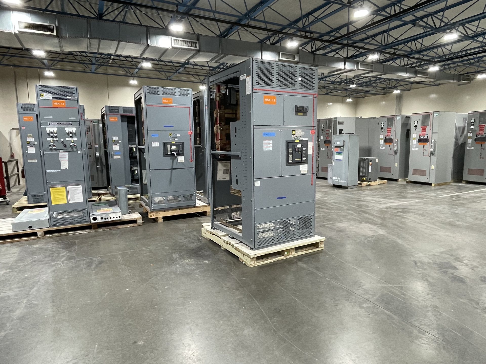
A new section or retrofit component must fit the actual assembly, not just a nominal equipment description. Document lineup arrangement, compartment dimensions, bus location and orientation, phase sequence, conductor access, barriers, and the space needed for cable routing and maintenance. Identify the manufacturer and model where known, along with any field changes that could affect mounting, clearances, or the connection between sections.
Interface review should also cover enclosure construction, environmental conditions, floor and anchorage requirements, access paths, and the way the proposed addition connects to existing bus and control wiring. Photographs can supplement drawings, but they do not replace dimensional and electrical documentation. State whether the project calls for a new adjoining section or new retrofit components, and flag any unknown interface conditions before requesting a firm scope.
Confirm Listing and Applicable Standards
An expansion can change the configuration that was evaluated or listed originally. Identify the existing assembly’s markings and documentation, then ask how the proposed new section or retrofit components affect the intended configuration. The applicable requirements depend on the equipment type, installation, and project jurisdiction. Listing status should be verified for the specific configuration; an existing label should not be assumed to cover every later modification.
UL 891 applies to switchboard assemblies; it is not a blanket listing for all low-, medium-, or high-voltage switchgear. Provide the equipment classification and the project’s specification requirements so the quotation and engineering review can address relevant standards and documentation. Any required evaluation, field review, or approval should be determined with the authority having jurisdiction and other responsible project parties.
Review Protection and System Coordination
Adding a feeder or section can alter fault paths, protective-device coordination, and the conditions under which downstream equipment is protected. Review the proposed breaker or protective-device function, settings and trip characteristics where applicable, upstream and downstream devices, and the system’s grounding arrangement. Confirm whether the addition affects selectivity, arc-flash studies, interlocking, metering, or required control and alarm signals.
Provide current one-line diagrams, coordination or protection studies, device schedules, control schematics, and the intended sequence of operation when available. If an operating mode or source arrangement is changing, describe it explicitly rather than assuming the existing study covers it. Protection settings, installation, testing, and energization must be handled by qualified personnel under approved project procedures.
Establish Available Capacity and Define Procurement Scope
Electrical capacity is a system question as well as a bus question. Confirm the service or source capacity, transformer and feeder limits, demand assumptions, and expected future load against the proposed addition. Identify whether the expansion is intended for present demand, planned growth, or a specific operating case. A physically compatible section does not resolve an upstream capacity constraint or establish that the full system can serve the added load.
For pricing, send the required ratings and functions, existing equipment records, interface drawings, site conditions, delivery constraints, and requested documentation. Specify American components if required by the project and have component origin confirmed for the quoted configuration; do not assume every part meets domestic-content rules or that compliance is certified. We supply new equipment and new retrofit components only. Engineering scope, availability, lead time, and test documentation are confirmed for each quotation.