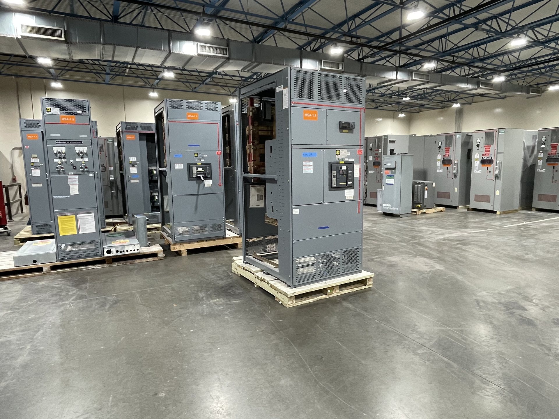
What a Ground Bus Is and What It Does
In a switchboard or switchgear assembly, the ground bus is a conductive bar intended to receive equipment grounding conductors and designated bonding connections. It gives those connections a defined point within the assembly and, when properly specified and installed, helps maintain electrical continuity among the components that the design requires to be bonded. The bus is distinct from phase conductors and the neutral bus: it is not intended to serve as a normal current-carrying circuit conductor.
The exact role depends on the assembly and its electrical system. The project documents should identify whether the bus connects to the service grounding and bonding arrangement, downstream equipment grounding conductors, enclosure sections, or other specified parts. Do not assume that every metallic part, neutral connection, or field conductor belongs on one bar. The one-line diagram, grounding details, equipment drawings, and applicable codes establish the intended arrangement.
Ground Bus, Neutral Bus, and Bonding
A neutral bus and a ground bus have different functions. The neutral is a circuit conductor in systems that use one; the equipment grounding path is provided for safety and fault-current purposes. Whether and where the neutral is bonded to the grounding system depends on the system configuration and the point of service. A downstream assembly may require an isolated neutral, while a service assembly may have a different bonding arrangement. The project engineer must define the correct relationship.
Treating these bars as interchangeable can create an unintended connection between neutral and equipment grounding conductors or leave a required bond out of the assembly. When requesting equipment, identify the service or feeder application, system grounding method, neutral requirements, and any specified bonding point. Provide the approved one-line diagram and relevant grounding notes so the manufacturer can review the bus arrangement against the intended configuration rather than infer it from a generic description.
Bar Material, Position, and Connection Details
Ground-bus design is more than selecting a bar and placing it in an enclosure. The submittal should clarify the required conductor material, bus material and finish if specified, mounting location, orientation, and how the bus relates to assembly sections and barriers. Identify the incoming and outgoing grounding conductors, their termination method, and any lug or hole-pattern requirements. If the installation has space constraints or unusual cable routing, include those details before the design is finalized.
The manufacturer also needs the project’s electrical and mechanical requirements to evaluate the proposed configuration. Relevant information can include assembly arrangement, conductor entry direction, section layout, available mounting space, and the project’s specified fault-duty or equipment ratings. Do not select bar dimensions or connection capacity from a generic glossary definition. Those details must be engineered and confirmed for the specific equipment, including compatibility with the assembly and its applicable standards.
Grounding Connections Across Assembly Sections
An assembly may consist of multiple connected sections, and the grounding path must be addressed across the complete lineup. Drawings should show how ground-bus sections connect to one another and how the assembly’s grounding point interfaces with the site grounding system. Where the equipment design uses shipping splits or field-connected sections, specify who supplies and installs the joining components and what connection details must be reflected in the final documents.
For a retrofit, describe the existing assembly, the affected section, and the intended connection point rather than requesting a bar based only on appearance. Provide available nameplate information, clear photographs, dimensional drawings, conductor details, and the relevant existing schematics. New retrofit components must be reviewed for fit and electrical compatibility; matching an old part visually does not establish that its material, connection arrangement, or rating is suitable for the updated application.
Documents to Include in a Ground-Bus Request
A complete request for pricing should identify whether the requirement is for a new assembly or a new retrofit component and state the application, voltage, current, service or feeder role, and system grounding method. Include the one-line diagram, grounding and bonding notes, equipment arrangement, conductor entry details, and specified lug or termination requirements. If the project requires American components, state that requirement explicitly and identify any applicable project criteria; component origin and compliance must be confirmed during quotation review.
Ask for the ground-bus arrangement to be shown in the proposed drawings and clarify which project documents will be supplied with the quotation or submittal. Confirm the intended bus connections, neutral isolation or bonding details where applicable, and any requested material or mounting provisions. Listing and applicable standards should be verified for the specific configuration. UL 891 applies to switchboards; it is not a blanket listing for every type of switchgear or every assembly.
New Equipment, Retrofit Scope, and Project Review
Switchgear Builders Texas manufactures new equipment to specification and supplies new retrofit components. For either scope, the ground-bus requirement should be tied to the project’s approved electrical design. A retrofit request should explain what is being replaced or added, whether conductors or enclosure sections are changing, and what documentation is available to verify the existing assembly and the intended grounding path.
We serve Texas from the United States and ship nationwide. Availability, engineering scope, component origin, lead time, and test documentation are reviewed for each quotation, so provide the required delivery destination and project schedule when requesting pricing. Installation, servicing, testing, and energization must be performed by qualified personnel under approved procedures. Final connection details and equipment documents should be checked against the project requirements before work proceeds.