Define the Fabricated Parts and Their Function
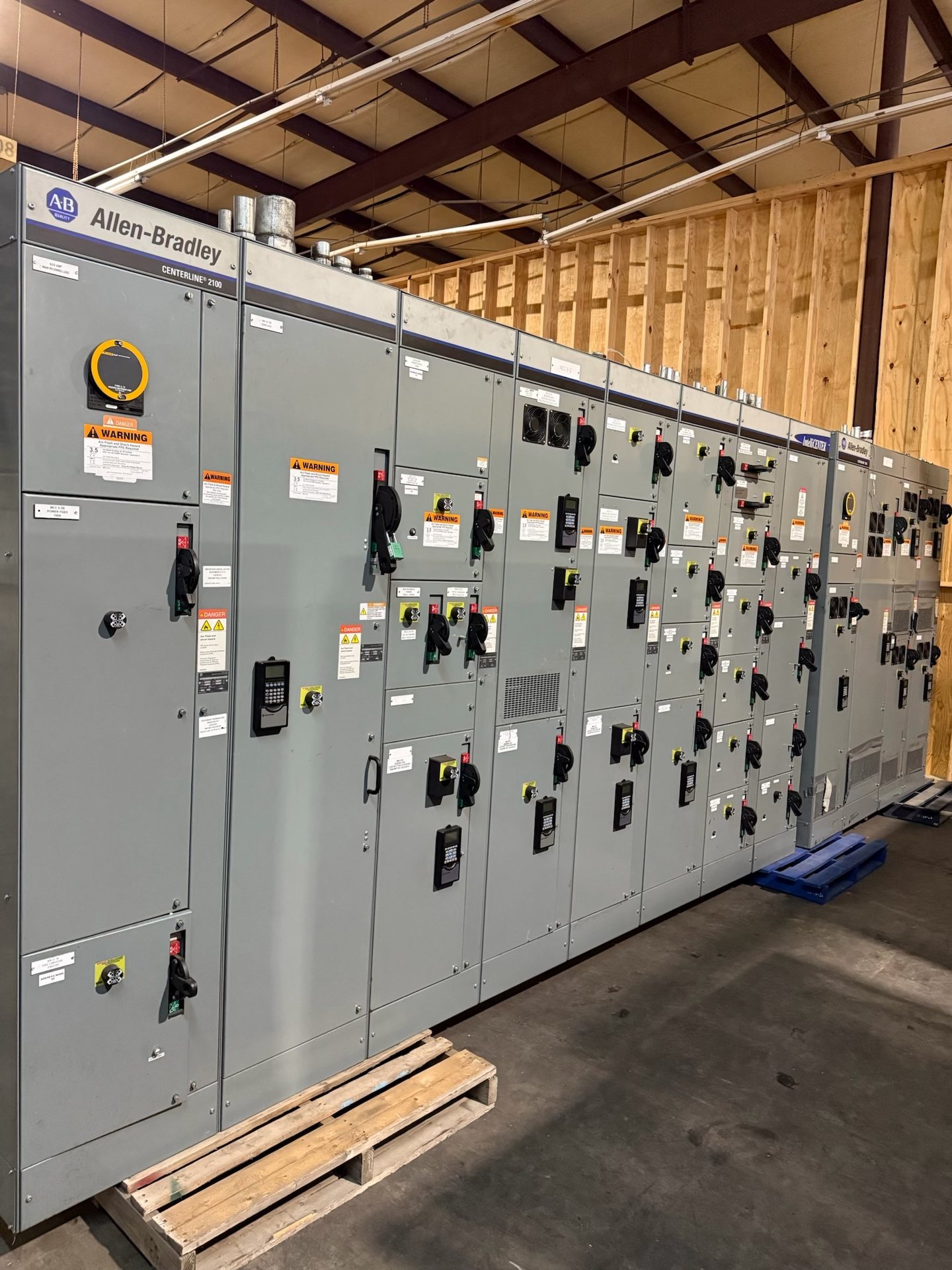
Sheet metal work can include enclosure sections, doors, covers, mounting panels, partitions, and internal barriers. These parts serve different purposes: an exterior panel may provide access and protection, while a barrier may separate functional areas or support the assembly’s intended arrangement. Before requesting pricing, identify which parts are included, whether they belong to a new switchgear assembly or a new retrofit component package, and how each interfaces with adjacent equipment.
The application affects the design brief. Clarify whether the equipment is indoor or outdoor, the installation orientation, cable entry direction, access and maintenance needs, and any stated environmental or project requirements. For replacement components, identify the equipment configuration and the parts being replaced without assuming an old part is a complete fabrication drawing. The manufacturer should review the available records and confirm whether further dimensions or engineering information are needed.
Select Material and Surface Requirements
Material selection should be documented rather than inferred from appearance. Specify the required sheet material and thickness where the project design establishes them, along with any finish or corrosion-resistance requirements. These choices affect stiffness, forming behavior, weight, and how a panel interfaces with fasteners or supporting members. If the design allows alternatives, state the acceptable range or ask for the proposed material to be identified in the quotation for review.
A finish can influence fit as well as appearance, particularly at folded edges, mounting points, and mating surfaces. Drawings or specifications should distinguish surfaces requiring a particular finish from areas where it is not critical. If American components are required, state that as a project requirement and request confirmation of the applicable component scope and documentation. Do not treat a general material description as independent verification of domestic-content compliance.
Plan Cutting Around the Drawing
Cutting defines the blank geometry before forming, so the released drawing should show the part outline, openings, slots, cutouts, and edge conditions needed for assembly. Coordinate hole and opening locations with the components they serve, such as mounting hardware, access features, or cable interfaces. Identify dimensions from clear datums rather than relying on measurements taken from an image or an unscaled print.
For a new retrofit component, provide the equipment identification, the intended mounting location, and any reliable reference dimensions or controlled drawings. Note whether existing fastener locations must be reused and which features are essential to fit. If the available information conflicts, flag the discrepancy for review before fabrication. This helps distinguish a confirmed interface from a field assumption and reduces the risk of producing a part that cannot be installed as intended.
Account for Forming and Assembly Fit
Bends change the relationship between the flat pattern and the finished part. The drawing package should make clear which dimensions describe the formed condition, identify bend locations and directions, and show the faces that must align with other components. Where the design depends on a flush surface, a door gap, or a panel meeting an adjacent frame, specify the controlling surfaces and dimensions instead of leaving fit to interpretation.
Formed parts may also need reliefs, returns, hems, or other edge details to meet the design and assembly interfaces. Confirm which features are required and how they affect nearby hardware, clearances, and access. When a component is part of a larger enclosure, review the assembled relationship—not only the individual sheet dimensions. Any proposed change to a bend, edge, or opening should be reviewed against the complete drawing package before it is accepted.
Communicate Tolerances and Dimensional Control
A useful drawing defines which dimensions are critical to fit and which can follow the drawing’s stated general tolerances. Identify datums, dimension the part in its intended assembled condition where appropriate, and state tolerance requirements for mounting patterns, mating edges, openings, and alignment features. Avoid conflicting dimensions or unspecified tolerances on features that determine whether a door, barrier, or panel will meet its counterpart.
Dimensional control is most effective when the project team agrees how a feature will be evaluated. Specify the relevant reference surfaces and whether the requirement applies before or after finishing, where that distinction matters. If a part must align with existing equipment, provide approved interface dimensions and identify their source. Review drawings and revisions as a coordinated set so that fabrication, purchasing, and installation teams use the same released configuration.
Review Documentation, Scope, and Delivery
A fabrication request is easier to evaluate when it includes the application, drawings with revision status, material and finish requirements, quantity, and required interface information. For an enclosure or barrier package, identify whether hardware and assembly are included or whether the request covers fabricated sheet metal only. For new switchgear, coordinate sheet metal requirements with the electrical configuration so that enclosure features and internal arrangements are reviewed together.
Before placing an order, compare the quotation with the requested drawings, material scope, component requirements, and documentation expectations. Ask what engineering review, availability, lead time, and test documentation apply to the specific configuration; these items require confirmation for each quotation. If the project involves a switchboard, verify applicable standards and listing requirements for the proposed assembly. Installation, servicing, testing, and energization must be performed by qualified personnel under approved procedures.