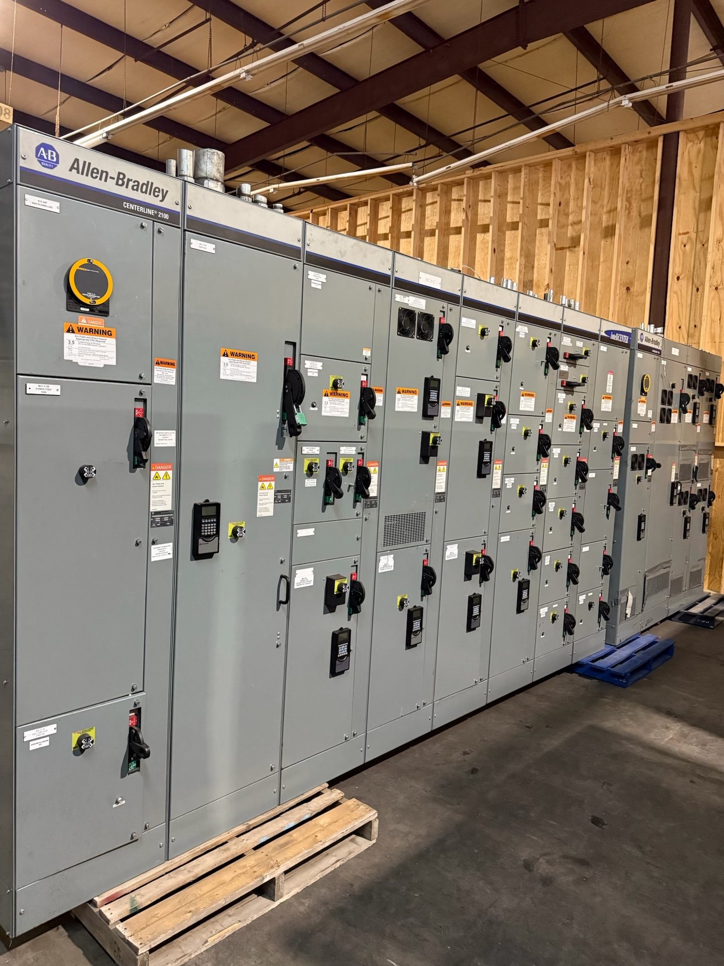
Switchgear for Utilities and Power Generation
Utility substations, generating facilities, and associated distribution systems can present very different electrical duties. A project may serve station auxiliaries, connect generation to facility loads, or distribute power among buses and feeders. Begin by defining the equipment’s role in the one-line diagram, nominal system voltage, available fault current, continuous load, and required operating functions. Those details establish the design basis for selecting an assembly and coordinating its components.
For a quotation, provide the latest one-line diagram, equipment schedules, project specifications, and relevant existing-equipment information. Identify whether the scope is new construction, replacement, or a retrofit using new components. Include the project location, delivery constraints, expected operating sequence, and required submittal documents. We build new equipment to specification; final configuration and suitability depend on review of the project requirements.
Match Equipment to Load and Duty
Generation and utility loads may include steady auxiliary demand alongside motors, transformers, pumps, fans, compressors, and other loads with distinct starting or operating behavior. Share load schedules and identify which loads are continuous, intermittent, essential, or subject to frequent switching. Ask the engineer of record to clarify applicable demand, motor-starting, and future-load assumptions so that the equipment design and protective-device coordination reflect the intended duty.
Utility-connected generation can also involve changing power flows, parallel sources, or operating modes that alter the distribution system’s requirements. Document expected source configurations and normal and alternate operating conditions rather than sizing around a single snapshot. Confirm that the proposed equipment rating, bus arrangement, and protective devices align with the approved study and project specifications. Ratings and configuration are determined during project review, not inferred from the page topic.
Define Source Arrangements and Bus Operation
Describe every normal and alternate source, including utility service, generator connections, transformers, and ties between buses. The one-line diagram should make clear which sources may operate together, which transfer or paralleling functions are required, and what interlocks or control interfaces the design must accommodate. These decisions affect the assembly layout and coordination requirements, so they should be settled early enough to inform equipment documentation and purchasing.
For projects with multiple operating modes, provide a sequence of operation that explains expected switching states and restrictions. Identify whether the equipment interfaces with external controls, metering, or supervisory systems, and specify the required signals and documentation. A proposed arrangement should be checked against the complete system design and applicable project standards. We can review the requested scope, but do not treat a preliminary quotation as approval of a protection or operating scheme.
Coordinate Protection and System Documentation
Protection requirements depend on system voltage, fault conditions, grounding, source behavior, and the roles of upstream and downstream devices. Provide the available short-circuit and coordination information, grounding assumptions, and protection criteria established by the project team. State which devices, trip functions, metering features, or control provisions are in scope. Where studies are incomplete, identify the responsible party and the information still needed before final design approval.
Review submittals against the current one-line diagram, equipment schedule, and written specification. Check device descriptions, ratings, bus and feeder designations, control interfaces, and any required accessory or metering provisions. Confirm what test records, drawings, and other closeout documents are required with the quotation. UL 891 applies to switchboard assemblies; it is not a blanket standard for all switchgear. Verify listing status and applicable standards for the specific configuration.
Account for Site and Operating Conditions
Utility and generation equipment may be installed in indoor electrical rooms, dedicated substations, plant spaces, or other environments with different temperature, moisture, dust, corrosion, and access conditions. Specify the installation setting and any project-defined enclosure or environmental requirements. Also provide space limitations, cable-entry preferences, working clearances, and route or rigging constraints that could affect the equipment arrangement and delivery planning.
Consider operational exposure as well as the room or enclosure: vibration, contamination, condensation, and limited access can influence maintenance planning and equipment requirements. Clearly distinguish mandatory site conditions from design preferences and provide the governing project documents. Do not assume an environmental rating or accessory is included unless it appears in the reviewed scope. Suitability must be confirmed against the actual installation conditions and applicable specifications.
Plan Procurement, Retrofit, and Maintenance
For new construction, align procurement milestones with approved drawings, interface requirements, delivery access, and the planned sequence of installation. For replacement work, document the existing assembly, dimensions, connections, device information, and the reason for replacement. Retrofit scope is limited to new components and must be reviewed for compatibility with the existing equipment and project design; a component should not be assumed interchangeable based on appearance or a partial identifier.
A maintenance plan should identify inspection responsibilities, required records, access needs, and the project’s approved procedures for taking equipment out of service. Installation, servicing, testing, and energization require qualified personnel working under approved procedures; this page is not a field-work instruction. For purchasing, request a project-specific quotation and confirm component origin, engineering scope, lead time, and documentation for the proposed configuration before release.