Coordinate the Utility Service Interface
Start with the utility’s written service requirements, not an assumed standard arrangement. The project team should identify the serving utility, service voltage and phase, point of delivery, ownership boundary, available connection method, and any requirements for utility access or isolation. Confirm whether the utility or the facility provides service conductors, metering provisions, and service disconnecting equipment, and document who reviews and accepts each interface.
For equipment selection, provide utility correspondence, service diagrams, the current one-line, and the project’s expected load and growth basis. Clarify whether the service will be installed for an initial phase or a final buildout, and whether future expansion must connect without replacing the main distribution assembly. Utility approval and equipment compatibility depend on project-specific review; a proposed configuration should not be treated as accepted until the responsible parties confirm it.
Define Main Distribution Sections and Operating Needs
Describe how the service enters the facility and how the main distribution section supplies downstream systems. The one-line should show the service main, feeder arrangement, bus connections, tie breakers if applicable, and planned connections to facility distribution. State which sources and operating states the equipment must accommodate, including any normal, alternate, or future source arrangement that is part of the design. These details shape section boundaries and the equipment configuration.
Also identify practical enclosure and installation constraints: indoor or outdoor placement, available footprint, cable entry direction, conductor access, and the room’s environmental conditions. Explain required clearances and how the assembly will be moved into position. Where phased construction is planned, specify which sections must be installed initially and how later sections are expected to connect. We build to the reviewed requirements; physical fit and interfaces should be checked against the project drawings before release.
Resolve Metering Requirements Before Configuration
Metering can be governed by utility rules, facility monitoring needs, or both. Identify whether revenue metering is required and who supplies, owns, reads, and maintains the metering equipment. Ask the utility for its requirements for meter location, access, instrument transformers, wiring provisions, test facilities, and separation from other equipment. Do not assume a meter socket, compartment, or arrangement is acceptable without confirmation from the utility and the project engineer.
For facility monitoring, specify the measurements and interfaces the project expects, such as service-level electrical quantities, communications requirements, or connection to a monitoring system. Distinguish owner monitoring from utility revenue metering so that each function has a clear responsibility and approved arrangement. Provide control or communications documents when available, and identify any space, wiring, or access provisions that must be reserved. The final scope should state what is included and what is furnished by others.
Establish Available Fault Duty at the Service
Available fault current is essential to selecting compatible service distribution equipment. Request the utility’s available fault-duty information at the point of delivery, including the basis and point at which it applies. The engineer should provide the system voltage, grounding method, transformer information where applicable, conductor lengths and impedances when known, and any source or operating scenarios that affect the calculation. A value without its location and assumptions may not describe the duty at the equipment terminals.
Submit the engineer’s short-circuit study or the information needed to coordinate the equipment review, and identify applicable interrupting, withstand, and protection requirements in the project documents. If utility data are preliminary, say so and establish who will provide the final values and by what design milestone. We do not infer a fault rating from a generic application description. The configuration and its documented capabilities must be confirmed against the project’s final available fault duty.
Provide Drawings, Loads, and Coordination Inputs
A useful quotation package includes the latest one-line, service requirements, equipment schedule, site or room plan, and written load basis. Show present and planned demand, major load categories, expected growth, and any known power-factor or harmonic considerations that affect the distribution design. Identify feeder quantities and conductor details when established, including the intended entry and termination arrangement. Mark unresolved items so they can be distinguished from approved design criteria.
Provide protection and coordination documents when available, including the design team’s requirements for protective devices and selective coordination. Clarify project submittal expectations, drawing review milestones, and the records needed for procurement and installation. If the schedule is driven by utility approval, construction phasing, or a data hall turnover date, identify those milestones without assuming a delivery date. We review lead time and documentation requirements for each quotation; both depend on the finalized scope and configuration.
Specify New Equipment and Retrofit Scope Clearly
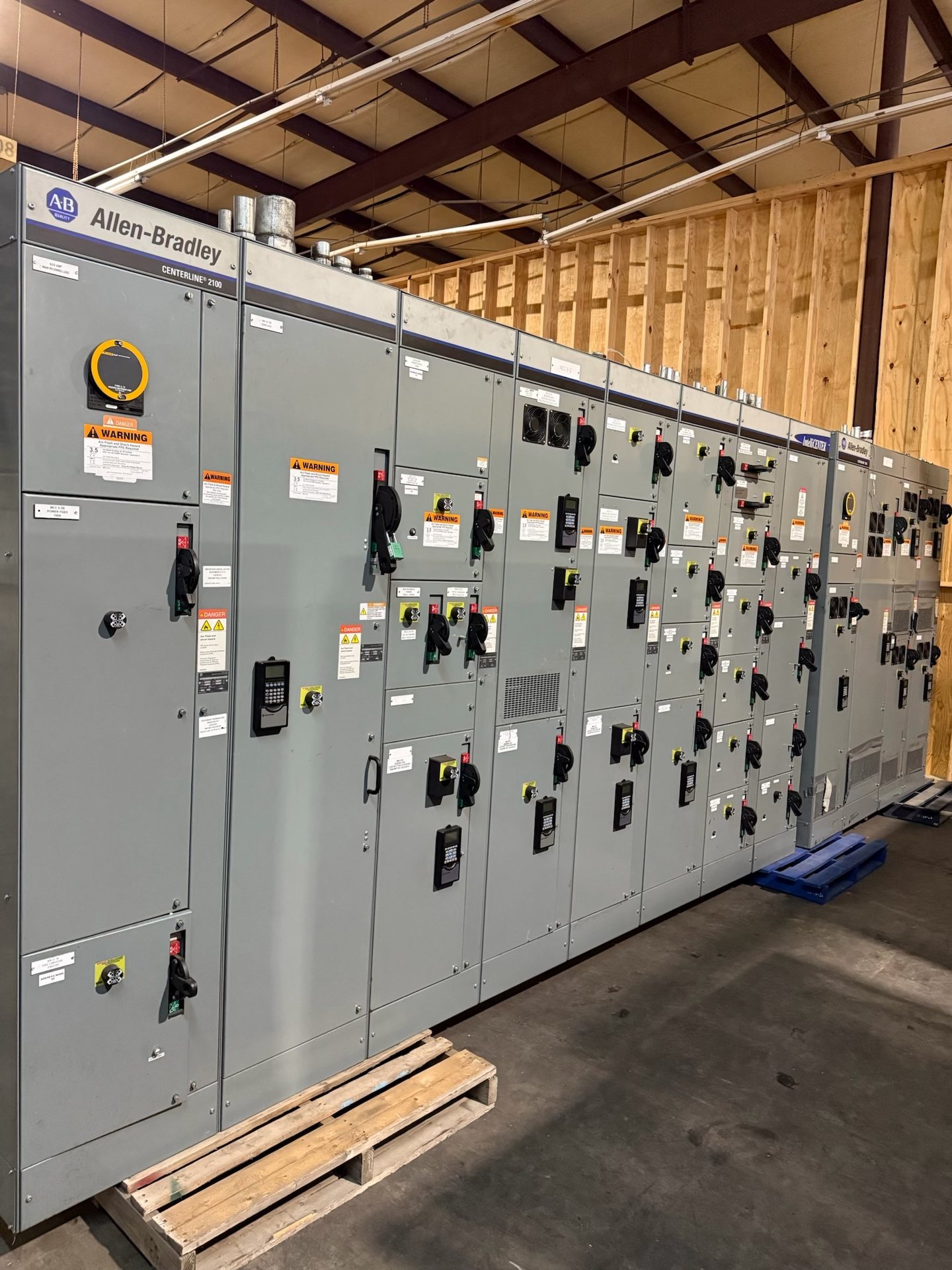
This page concerns new utility-service distribution equipment and new retrofit components only. For a retrofit, identify the existing assembly manufacturer and model if known, nameplate details, dimensions, bus and connection information, and the sections or interfaces affected. Include clear photographs and existing drawings where available, but do not rely on photographs alone to establish compatibility. The project team should verify field conditions and define the boundary between new components and retained equipment.
For either new construction or a retrofit, request pricing against a defined scope and list any exceptions or open engineering questions. State the requested component origin and provide applicable project requirements, while recognizing that origin, availability, and supporting documentation require confirmation for the quoted configuration. UL 891 applies to switchboards; it is not a blanket standard for every switchgear assembly. Verify applicable standards and any listing requirements for the specific configuration, along with the test documentation available for that quotation.